FIGURE 1. Typical BMD mission
One of the world’s most complex undertakings in the past two decades has been the US Army Ballistic Missile Defense Program. A critical part of the large research and development investment in this program has been the effort to develop data processing hardware and software technologies to meet the computational challenges of this incredibly complex problem. The demands for a computing system that will deliver a throughput of hundreds of millions of instructions per second at some undetermined point in its life cycle,.with a high confidence that correct execution will occur, challenge even the most advanced technologists.
Any program of this magnitude is bound to foster technology advance, but the severe computational requirements of the BMD problem have been an exceptionally rich source of learning in data processing. The BMD program began in the late 1950’s with an assessment of the feasibility of hitting an object entering the atmosphere at reentry velocities. [1] During the 1960’s, a massive effort was undertaken to develop the first operational BMD system, Safeguard. This system prompted development of the central logic and control—CLC—a multiprocessor tailored to meet the needs of the defense problem. Research and development continued in the 1970’s with the Site Defense Program. This program applied a large mainframe computer, the CDC 7700, to the complexities of endoatmospheric defense. These programs and companion advanced technology efforts provide valuable experience from which requirements for the technology of the 1980’s can be derived.
The goal of a BMD system is to either deny the enemy the ability to damage a defended region, or extract from him an unacceptably high price for defeat of the system. A BMD system typically consists of sensors to observe and collect data about a threat, a kill mechanism to render the threat ineffective, and a computational element designed to ensure a cooperative effort from the component parts.
THREAT DEFINITION. An object on an intercontinental ballistic trajectory will have a flight time of around 30 minutes. The flight begins with a rapid acceleration up through the atmosphere until the rocket engines burn out and the reentry vehicle is deployed. The entire threat complex, consisting of the RV, decoys or penetration aids designed to confuse the defense, nuts, bolts, panels, and even portions of the missile upper stages, coasts above the atmosphere. Upon reentry into the atmosphere, the threat complex experiences severe heating and a rapid rise in dynamic pressure during deceleration. This may result in a further breakup of the threat complex into a shower of literally thousands of objects for each booster load. From this cluttered environment the BMD system must select the object with the warhead inside.
The threat vehicle is beyond the atmosphere for 90 percent of the flight time. Interdiction during this flight region gives the benefits of early warning and long engagement times. Drawbacks for exoatmospheric engagement include the complexities of operating in space, the need for highly sensitive sensors, and difficulties in keeping the sensors on station. These factors force consideration of a defense strategy focused on the reentry portion of the flight. Such a strategy has the advantage of allowing the atmospheric interaction with the threat complex to aid in the sorting out of threatening from nonthreatening objects. The price for this benefit comes high: the time to engage, detect, track, and destroy the target is reduced to around 30 seconds. Furthermore, this engagement takes place in a flight regime where reentry phenomenology must be observed very precisely amid a high degree of clutter.
It becomes obvious why throughput remains a paramount characteristic for any BMD computer architecture after considering the time frame and volume of traffic that must be processed. The required resources can be estimated by considering just the objects being tracked. The algorithm that updates the state vector of an object requires about 3000 CPU instructions. This algorithm must be executed after each radar track pulse. For 300 targets, each tracked at 20 Hz, 18 million instructions per second of processor throughput would be required, plus the capability required to handle the other operations in the sequence.
THE DEFENSE SYSTEM. A terminal defense system illustrates the complexities of BMD. The main system sensor is a phased array radar that can generate a pencil beam pointable, within a few microseconds, in any direction within the surveillance volume. Beams are either transmit or receiver beams; each transmit beam can generate any one of a number of different pulse configurations (carrier frequency, number of pulses, pulse coding, frequency modulation, pulse length, etc.). Each receiver beam can likewise assume any one of a number of configurations (carrier frequency, range extent, matched filter, etc.). Typically, the radar generates several thousand transmit beams per second and a proportionate number of receive beams. Generally, several hundred transmit and receive beam pairs are reserved for searching the upper part of the surveillance volume. These are generated in a raster scan pattern designed so no object can penetrate the volume without detection by at least one search beam. A variety of special beams are interleaved randomly in both time and space among the search beams, as required by the target environment and battle situation. These verify search detections, provide precision tracking of previously detected and acquired targets, transmit guidance commands to interceptors, perform target discrimination and classification, and perform several other functions.
An object entering the search volume is first detected by a search-verify pulse sequence (Figure 1), which eliminates ghosts and provides information for filtering out most nonthreatening targets. After this initial filtering operation, the radar objects deemed potentially threatening are reported to the computer for further processing. Upon receipt of a target report from the radar, the computer initiates a file on the object and periodically requests radar transmit pulses to gather additional information about that object. Immediately following file establishment, the computer directs several beams at the predicted object positions in order to establish initial time-tagged position and velocity coordinates (state vector) for that target. The target is then placed in precision, or closed loop, track. The position information for this track must be updated frequently (e.g., tracking at 20 pulses per second would require less than 50-millisecond response). For each update, the computer must search the files in some sort of priority fashion, then calculate and transfer a detailed beam generation order to the radar. After the target has been in precision track for a short interval, discrimination routines, and possibly special radar pulses, are employed to determine whether or not the target is a warhead. If so, precision track is continued. If not, the target file maintenance is continued at a low track rate to prevent the above operations from being repeated on targets already determined to be nonthreatening.
This description refers to the processing of a single target. At any time, there may be tens of thousands of object images in process. Some of these will be in precision track, some in discrimination, some in maintenance track, and others in track initiation. In addition, objects continually appear in the system during subsequent observations. These redundant objects must be tracked, updated, correlated, and eliminated.
FIGURE 1. Typical BMD mission
COMPUTER CHARACTERISTICS. What characteristics must a data processing system have to satisfactorily perform in the BMD environment? [2] The following emphasizes a few of the major considerations in developing computational capability for BMD.
Throughputs. The capacity of a given computer architecture must be able to handle the instruction mix required by the algorithms in a given construct, and handle this mix concurrently for the many processing threads dictated by the overall system load. In the past, capacity was only available in large mainframe machines.
Fault tolerance/graceful performance degradation. A BMD computer system must be designed to produce extremely high confidence in all system components. It must also possess very high reliability: once up, there must be a high probability that the configuration will stay up long enough to conduct an entire engagement. Computer architectures for BMD must be able to tolerate hardware failures during mission initialization and operational modes. Should one component in the BMD computer architecture fail during an engagement, the remainder of the system should be capable of continuing execution, albeit at a slower rate and with accompanying reduced system effectiveness. For these reasons, as well as those related to increased throughput, BMD computer designs typically employ multiple processor configurations. At the same time, reliability considerations dictate minimizing the number of elements that could fail in a computer system, thereby tending to constrain the configuration toward centralized architectures. Solutions to these conflicting goals have ranged from “hot spare” redundancy of computer hardware components to increased attention to high-reliability parts.
Growth and flexibility. The accelerating evolution of the threat to which a BMD system must respond has led to a need for architectural features that enhance the ability to add processors as more processing is deemed necessary. This must be done in a way that supports the natural growth of the system during its definition as well as in the field.
1960’S APPLICATIONS. The BMD program in the 1960’s focused on the development of the Safeguard system, which provided defense for US Minuteman ICBM bases. [3] The system contained a perimeter acquisition radar, a missile site radar, arid a ballistic missile defense center. The PAR, a long-range, single-face, phased array radar, performed long-range surveillance, detection, and tracking. The MSR used PAR-generated information correlated with its own data to perform the functions of track and guidance for the Sprint (short range) and Spartan (exo-atmospheric) interceptors.
The Bell Telephone Laboratory custom designed and Western Electric built the central logic and control computer, which supported the PAR and MSR. The CLC was designed to control the adjoined radar, support tracking of reentry vehicles and interceptors, perform engagement planning, target discrimination, and a wide range of error control and system recovery checks. The CLC would certainly qualify as a supercomputer of its era, since it was designed in the early 1960’s based upon 1965 technology. The CLC was designed when 1.5 million instructions per second was pushing the processor state-of-the-art. Multiprocessors held promise of providing the order of magnitude increase in throughput required to address a problem with a peak throughput of about 10 million instructions per second and a peak input/output transmission (for radar control) of about 10 thousand 64-bit words per second. The CLC is a multiprocessor in the classic sense, having 10 processors in two partitions capable of operating as independent computing systems. The BMD problem was mapped on the CLC as a relatively large number of short (under 500 instructions) tasks randomly distributed throughout the memory. Under control of a tactical operating system, the computer was divided into a green partition that executed the weapons system software, and an amber partition that contained the software exerciser. The net result was a software system of 735,000 real-time instructions, 580,000 statements of support software, and 830,000 installation and maintenance instructions. [4]
CLC architecture. Figure 2 outlines the basic computer architecture of the Safeguard BMD system. The CLC has five basic types of components. The configuration design supports up to 10 central processing units, 16 program memory units, 16 data memory units, two timing and status units, and two input/output controllers. The timing and status unit provides real-time clock pulses and timed-event initiation as well as logic to sense any failures in other computer elements. The TSU is also one node of a flexible, distributed switching network connecting all computer components. The switch network allows the TSU to reconfigure the system in real time after sensing a component failure. Communication between components is through the input/output controllers. Computer element-to-element signalling uses an asynchronous re-quest/acknowledge protocol. All processors can access memory simultaneously; conflicts between memory modules are resolved in a sequential-FIFO manner.
The CLC computer, configured as described above, remains in continuous operation with a radar early-warning system operated by the US Air Force near Grand Forks, North Dakota. It is an important testament to the soundness of the design that, in spite of its complexity, the CLC has remained in use 24 hours a day, seven days a week, for nearly 10 years—without significant hardware failure.
CLC throughput. In addition to multiprocessing, the CLC innovations included separate data and program store as well as interleaved memory to enhance throughput. Each unit consists of 32K single words of 34 bits each (two bits parity). Cycle time is 500 nanoseconds. Each program store unit is divided into two memory interleaves so consecutive locations in an instruction stream are stored in separate banks of the memory. This feature is necessary to support the CLC’s processor/memory interleaving approach to multitasking, and effectively doubles the instruction stream rate to processors.
Basically, the implemented strategy consisted of storing only one copy of a software task in the program stores, while allowing multiple instances of that task to be in execution on several processors at once, each processor accessing the same set of instructions. This approach was possible because all application software routines were designed to be reentrant code. The separation of instruction memory and data memory greatly facilitates non self-modifying code construction, although re-entrancy was not the principal reason for two kinds of memory. This strategy works well except in those cases involving program store queueing, which occur when multiple instances of a frequently running task (e.g., tracking filters) attempt simultaneous access of the same instruction location. In such a case, the memory conflict priority logic internal to the program store resolves and buffers requests, but the queued task’s execution is, in effect, blocked until the instruction fetch is satisfied. Other than a restructuring of the software tasks into collections of subtasks for placement in separate program stores, the only solution was to allow multiple copies of a task to reside in separate program stores. But redundant copies of code occupied rather scarce storage. All three of the above techniques were implemented for the CLC architecture. The ultimate speed/memory conservation trade involved using multiple program copies only for tasks with the most stressing response times.
FIGURE 2. Safeguard central logic and control configuration.
In contrast to the sequential instruction fetch/operand fetch/execution process operation typical of von Neumann architectures, each CLC processor contains three separate control units that operate asynchronously. In effect, the three, units permit parallel fetching of instructions and overlapping of data with execution. A program control unit prefetches instruction words from a . program store into a four double-word instruction stack. For those instructions involving operand access, an operand control unit addresses the variable store to make available all addresses in the instruction stack. For instructions involving computations, the arithmetic control unit performs the required fixed-point or floating-point arithmetic. An added speed enhancement is the capability to execute short loops from the instruction stack itself, thereby precluding memory fetches for instruction loops shorter than four double words in length.
CLC reliability/availability. The operational concept of the Safeguard system required extremely stringent availability and reliability constraints. For example, the switch-to-spare time requirement was about one second, the fault-isolation time requirements were around 15 minutes, and the mean-time-to-repair requirements were on the order of four hours for 90 percent of all faults. These were met in the CLC through a combination of hardware redundancy, software control to aid in rapid reconfiguration, and a separate maintenance and diagnostic computer to aid in rapid fault detection.
Flexible partitioning is a key feature to the enhanced availability in the CLC. Under software control, the CLC can be configured into two partitions of arbitrary size, each capable of operating as an independent system. Reconfiguration is possible even while the tactical software is executing, within one second. The use of the partitions depends upon whether a mission is a simulation or an actual engagement. The partitions are designated green and amber, the latter having the smaller number of memories and processors. Each partition has a separate timing and status unit and input/output controller. A master-slave convention between TSUs was established; partitioning signals for automatic reconfiguration originating in the master (green) unit take precedence. Otherwise, the TSU in the amber partition would attempt to switch a functioning component from the green partition into amber when an amber component malfunctions. The CLC employs an n + 1 redundancy concept in which each of the five types of CLC components has a replacement unit not required for execution of the tactical software. These hot spares are in the amber partition. As the tactical or exercise simulation software executes, the TSUs receive status on the components in their respective partitions. When the green partition TSU detects a component malfunction, it automatically switches the failed unit into amber, bringing its n + 1 counterpart into green. The amber TSU then isolates the failed unit from the rest of the amber partition, and signals the maintenance and diagnostic subsystem. This subsystem performs diagnostic checks on the failed unit, isolating the failure to the line replacement unit level.
The fundamental shortcoming in this implementation is that if a unit fails during the execution of the tactical software, the switch out of the green portion uses a system recovery mechanism that halts the entire software weapons process, not just the software in the failed unit. Once halted, the software process has to undergo a complete re-initiation. While the hardware could reconfigure itself within one second, the software process requires on the order of 10 to 20 seconds to restart, depending on the number of processors in the green partition at the time. Thus, while the recovery mechanism is very well suited for real-time reconfigurations during system exercise and standby modes, its effectiveness during an engagement would have been limited.
Evaluation of the CLC. The basic CLC architectural features of partitioning, n + 1 redundancy, and switching proved to be sound. The multiprocessor approach provided adequate throughput but its unique structure created the need to use short-running low-priority asynchronous tasks in order to reduce task scheduler conflict problems. These and other factors led to a software system that had a relatively complex structure and proved difficult to modify without large amounts of software breakage.
The degree to which the system could be expanded has never been fully resolved. It is apparent that additional processors accessing the same set of instructions would increase the probability that program store queueing would occur. Data locking may also occur as these additional task copies contend for data. Simulations of a 15-processor configuration showed a 10 percent degradation from expected performance increase. [5] The initial trades relating to multiple copies could be redone to accommodate more processors, but the increased performance potential of this strategy was not fully investigated.
The maintenance and diagnostic subsystem proved to give a high degree of hardware fault detection and recovery. The benefits of approaching fault detection and recovery as one of the initial design requirements of the computer were apparent. This level of detection would have been virtually impossible without providing the mechanisms for data collection as an integral part of the design. The concept addressed only certain permanent hardware faults, and it was .felt that additional benefit could be derived from extending it to a wider class of timing faults. The containment and recovery of associated software faults were not addressed, but the need became clear during the project.
The CLC development was a pioneering effort to develop a special-purpose multiprocessor for an incredibly complex computing job. The optimism that pervaded the computer world in the 1960’s gave way to the understanding that multiprocessor systems as configured would not provide the whole solution to the expanding superproblem environment.
1970'S APPLICATIONS.
During the late 60’s and early 70’s, the BMD program entered an advanced research and development phase directed toward endoatmospheric defense. The system construct under development was site defense, designed primarily for protection of Minuteman silos. The Site Defense Program represented a completely different system construct from that of Safeguard.
Since the SDP was based upon an endoatmospheric engagement of the threat, the defense system was provided more time for threat evaluation. The radar power requirements could be scaled down considerably, and the interceptor fly-out region substantially reduced. However, reduction of the acquisition altitude dictated that initial data gathering tasks be conducted in regions of considerable atmospheric effects, causing substantially increased loads on the data processing subsystem. These loads were introduced through significant increases in traffic in a high-clutter environment of tank fragments, decoys, and countermeasures. Increased data about reentry signatures and an increase in threat size and complexity led to a further escalation of problem complexity.
The change in strategy from a few long-range area defense weapon systems to a much larger number of shortrange point defense systems imposed other constraints on the terminal defense system. First, to be effective, the short-range system had to be located in close proximity to the installation it was intended to defend, whereas the long-range system could be located on the periphery of the defended area. The necessity to locate the short-range system in the middle of the impact zone dictated unmanned operation. Second, the decision to defend a particular installation rather than an area made the deployment pattern for the defensive system quite sensitive to changes in the deployment pattern of US offensive weapons, thereby creating a need for a rapidly deployable system. Third, the decision to defend many military installations rather than a few large areas dictated a need for many systems, making cost a very important consideration. The need to minimize development, installation, and operational costs—even to the point of accepting some degradation in performance—required the utilization of commercially available computers and the implementation of a dormant mode of operation. At the inception of the Site Defense Program, most of the technologies required were available; however, the capabilities required to meld these diverse technologies into a single cooperative system had not been demonstrated. Therefore, it was decided to build and test a prototype system prior to initiation of a full-scale engineering development program, as is customary in the development of any large weapon system. Large mainframe machines had demonstrated high-throughput calculation capability, but reliability and dormancy requirements had not been demonstrated. Preliminary studies showed that although no commercially available computer would meet full tactical requirements, Control Data Corporation’s 7700 would be suitable for the prototype system.
CDC 7700 architecture. The CDC 7700 is capable of executing in excess of 19 million instructions per second. [6] Memory configuration is hierarchical. Each of the two central processing units contains a small core memory of 64K words and obtains data from a bulk-storage, non-executable large core memory (Figures 3 and 4).
FIGURE 3. CDC 7700 configuration.
FIGURE 4. CDC 7700 CPU layout.
Each SCM consists of 65,536 60-bit words arranged in 32 independent but interleaved banks of 2048 words each. The maximum SCM to LCM transfer rate is 27.5 nanoseconds per word. Each SCM can be addressed by its companion CPU. The large core memory of the 7700 computer has a 512,000 60-bit word capacity organized into eight banks of 64,000 words each, with a 1760-nano second read/write cycle time. Eight words are fetched from LCM to SCM with each reference, thus effecting a 27.5-nanosecond per word transfer rate.
Each CPU contains a 12-word (maximum of 39 instructions) instruction stack, 24 operating registers, and nine independent functional units, all operating on synchronous internal logic with a 27.5-nanosecond clock period.
Each CPU/SCM pair is connected via an I/O multiplexer to several peripheral processor units. The PPUs act as stand-alone processors to interface external hardware with the central processor. The PPUs are physically connected to both CPU/SCM pairs, but the logical connectivity is activated via the PPU software.
Communications between any executing programs are handled by PPUs. Tasks executing in each CPU cannot communicate with each other directly through the LCM. Several items of special equipment were added to the commercial computers, principally a setable internal clock for use as a time standard and to provide access to the radar time source.
CDC 7700 throughput. The systems technology computer architecture has two segmented CPUs (Figure 4). The usual sequential instruction execution control logic within the CPU is replaced by nine independent units: boolean, shift, normalize, floating add, long add, floating multiply, floating divide, population count, and increment. Since each functional unit receives instructions in parallel, nine separate instructions can be in execution at the same time. Furthermore, each of the functional units is subdivided into multiple sections. The output of each hardware section is an intermediate result that is input into the next of the sequentially linked sections. The sequential execution within a functional unit led to the term “pipeline machine.” The important characteristic regarding such a configuration is that a new instruction can be introduced to a functional unit at each clock pulse. Thus, for a functional unit containing four sections, four separate instructions could be in different stages of execution within the pipe at the same time. The combination of nine independent pipes and an input each clock cycle offers a tremendous potential speed advantage.
The functional unit input capacity is aided by an instruction word stack within each CPU. The IWS consists of twelve 60-bit registers. It is filled two words ahead of the program address being executed; consequently, program loops of up to 10 instruction words can be executed from the IWS itself without paying an SCM access time penalty.
The IWS receives its input from small core memory. The SCM contains the programs and the data files currently in execution on the CPU. The read/write cycle time for the memory is a relatively fast 10 clock pulses, or 275 nanoseconds. The SCM is partitioned into 32 independent banks of 2K 60-bit words each. The partitions are used to interleave consecutive instruction addresses across the 32 banks. This feature permits rapid fetch of instructions to the IWS as well as read/write cycle overlapping.
In addition to the two SCMs, the LCM contains the programs and data files awaiting dispatch to SCM when processor resources become available. The LCM contains 512K 60-bit words consisting of eight independent banks of 64K 60-bit words each. In spite of the relatively slow read/write cycle time of 64 clock periods (1760 nanoseconds), the interleaving permits a maximum LCM-to-SCM transfer rate of one word per clock period (27.5 nanoseconds).
The architecture also contains separate peripheral processing units to handle I/O. The control section of the CPU can delegate data transfer directly to an independent, programmable channel controller. With the CPU itself never slowed down by time-consumιing communications management activities, its timeline can be devoted entirely to “number crunching.” The combination of all these architectural features is a computer configuration with demonstrated throughput on an actual BMD instruction mix in excess of 19 MIPS, or million instructions per second.
Use of this architecture in second-generation BMD software revealed certain limitations in the configuration. This organization becomes inefficient if some jobs require a processing sequence different from that implemented in the pipelines. Data dependencies within a job, such as conditional branching, adversely affect the look-ahead process, thereby reducing the execution efficiency. The handling of interrupts was difficult with this architecture, since several instructions may be in a pipeline when an interrupt occurs. In such a case, preserving the state of the machine became a nontrivial problem leading to decreases in system response times, throughput, and overall system efficiency.
Although it did not prove to be a problem in the Site Defense Program, there is an inherent growth potential limitation in the CDC 7700 architecture. The basic CDC 7700 was designed to handle an assemblage of three CPU-SCM components of which only two were installed; thus, at least theoretically, the CDC 7700 has a potential for growth of approximately 30 percent over requirements of the prototype demonstration program. However, expansion beyond the third CPU-SCM combination would be costly, and there is a practical upper limit on the number of units permissible.
CDC 7700 availability / reliability. The CDC 7700 was made from commercially available components in production and widespread use for some time and was the most reliable large-scale data processor available. This application enjoyed the benefits of completely debugged hardware and adequate supporting software. The CDC 7700 components utilized discrete transistor technology, modular flatpacks for LCM, and core SCM; consequently, it was not amenable to a dormant mode of operation, and system reliability was less than desired. However, after improved maintenance procedures were implemented toward the end of the program, MTBFs adequate to meet tactical requirements were actually recorded. The most frequent failures were memory elements, and the largest class of errors were hard parity errors.
A number of techniques for enhancing reliability evolved and undoubtedly would have been incorporated into the CPU had the system gone into production. For example, the manufacturer proposed repackaging the machine using LSI technology and predicted that such repackaging would increase throughput by a factor of two, MTBF by a factor of eight, make a dormant mode of operation possible, and be fully compatible with existing software. In conjunction with this redesign, better error detection and correction schemes would have been employed. Single error correction/double error detection circuitry would certainly be included in any major redesign effort. This hardware senses and automatically corrects single parity errors within a one-word data transfer. The logic generates a hardware interrupt upon sensing a dual parity error within a one-word transfer, but performs no dual error correction.
Evaluation of the CDC 7000. In spite of its shortcomings, all of which are correctable with current technology, the CDC 7700 performed its mission well. The Site Defense Progam demonstrated that a commercially available, large mainframe computer could be adapted to the complexities of the BMD environment as currently defined. The BMD environment, however, is not a static quantity. It is continually aggravated by an ever-in-creasing assessment of enemy capabilities and ameliorated by continually evolving technological advances.
BMD REQUIREMENTS FOR THE 1980'S.
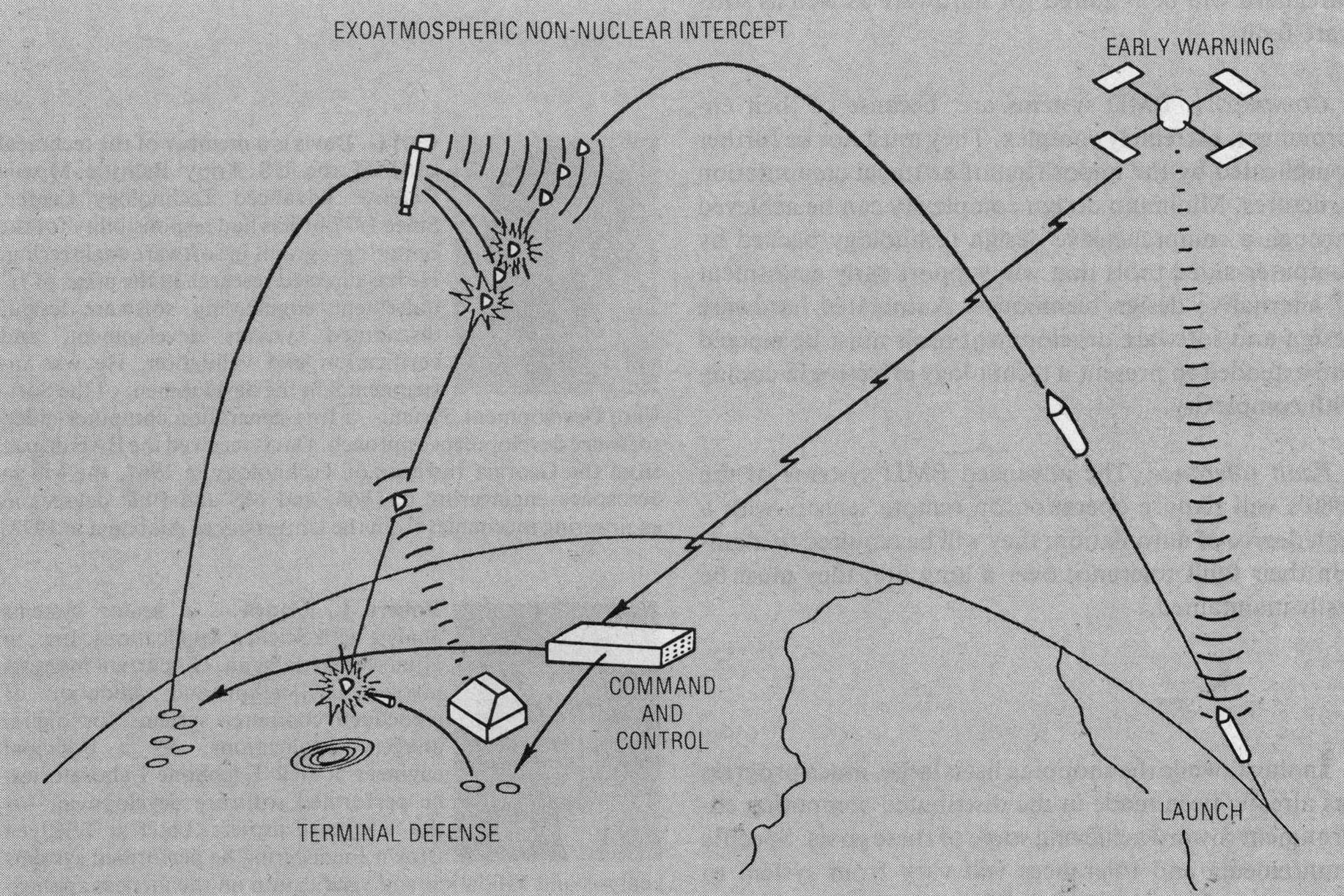
FIGURE 5. Layered defense concepts.
The BMD environment of the 1980’s will evolve toward a more open-ended broadly based technology program. This will involve a wide variety of system and technical approaches aimed at improving the kill probabilty throughout the ballistic flight regime. A new two-tier defense strategy will combine the endoatmospheric approach of site defense with an exoatmospheric overlay system. This layered approach (Figure 5) will provide a large improvement in BMD effectiveness, but will depend upon improved technology in sensing, killing, and most importantly, in data processing. Innovative endoatmospheric concepts will be pursued to increase survivability of a system through replacement of a few vulnerable radars with a network of smaller ones. Advanced exoatmospheric systems with highly sensitive long-range sensors will require supporting data processors functioning at extremely high rates. Extreme levels of geographical and functional distribution will be required of the computing complexes to support these constructs. [7] While technology has continued to provide an ever expanding base, it has not kept pace with the development of defense strategies.
Throughput. The need for higher effective computational rates will continue to increase, driven by the increasing complexity of defense solutions. As an example, the processing of exoatmospheric sensor data will require an onboard computer of between 50 and 100 MIPS contained in a space of less than two cubic feet. New BMD strategies will demand distributed systems of highly reliable components combined in a machine which will perform at the desired rates. The design of the machine must encompass hardware and software in a total entity.
Flexibility. Raw throughput, however, represents only a small and perhaps the most readily achievable part of the requirements: the complex system of the 80’s will require much more resilience. Changing environments will drive the need for a solution able to perform over a wide (often unexpected) input range. First, this means the systems must be designed to provide a close initial match between the hardware structure of the solution and the structure of the problem. Second, correlation must be maintained under changing requirements. Further, the software must conform strongly to that structure, providing an easily modifiable and adaptable framework. Concepts of load shedding through dynamic reconfiguration may be required to support the real-time aspects of a system capable of reconfiguring itself during an engagement to meet unexpected conditions.
Growth. BMD systems will experience growth, due to expanding requirements as well as the ever present underestimation of the problem size. Growth rates of several times the original estimate must be accommodated, and growth must be much more incremental and continuous than in the past. A natural evolution of system requirements would prevent costly breakage and redo of hardware and software components. This means the custom build philosophy characteristic of previous BMD configurations must be altered to encourage the construction of widely differing systems from sets of kernel processing components that can adapt and grow with the problems.
Reliability and availability. The requirements for dormancy, availability, and reliability will strongly affect the supercomputers of the 80’s. Capability for rapid fault detection, isolation, and reconfiguration must enable quick repair of faults. Networks of processors will be required where spare components are easily called into service. Extensions of the n +1 concept applied on Safeguard will be required for hardware as well as software faults.
Complexity. BMD systems are, because of their environment, extremely complex. They must not be further complicated by the imposition of artificial computation structures. Minimum design complexity can be achieved through a comprehensive design technology backed by computer-aided tools that will support early assessment of alternative design techniques. Automated hardware design and software development tools must be merged and extended to present a technology effective in coping with complexity.
Fault tolerance. The advanced BMD systems of the 1980’s will require operation on remote sensors with a high degree of automation; they will be required to maintain their fault tolerance over a long life; they must be easily maintained.
In short, while the shopping list is large, much progress has already been made in the distributed computing environment toward achieving some of these goals. Specific requirements and tolerances will vary from system to system, but the technologist will not suffer from lack of application of his technology. ■
We would like to acknowledge the help received from Mike Mariani, TRW; Fred Hudson, IBM; and Buddy Dace, BMDATC. Their help in stimulating discussions, written input, and positive critiques is greatly appreciated.
1. William A. Davis, Jr., “Ballistic Missile Defense into the Eighties,” National Defense, Sept. 1979, pp. 55-63.
2. Carl G. Davis and Charles R. Vick, “The Software Development System,” IEEE Trans. Software Eng., Vol. SE-3, No. 1, Jan. 1977, pp. 69-84.
3. “SAFEGUARD Data-Processing System,” special supplement, The Bell System Technical J., 1975, pp. S1-S269.
4. “SAFEGUARD Software Verification and Validation,” final report, Contract No. DAHC60-72-C-0092, Science Applications, Inc., Huntsville, Ala., June 1976.
5. John Mitchell, Charles Knadler, Gary Lunsford, and Steven Yang, “Multiprocessor Performance Analysis,” AFIPS Conf. Proc., Vol. 43, 1974 NCC, Chicago, Ill., pp. 399-403.
6. “Preliminary Hardsite Demonstration for the Advanced Ballistic Missile Defense Problem,” Control Data Corporation, Pub. ADD 324.
7. C. R. Vick, “A Next Generation of Supercomputers: From Mainframes to Micros,” EUROMICRO 80, London, England, Sept. 1980.