FIGURE 1. Safeguard components.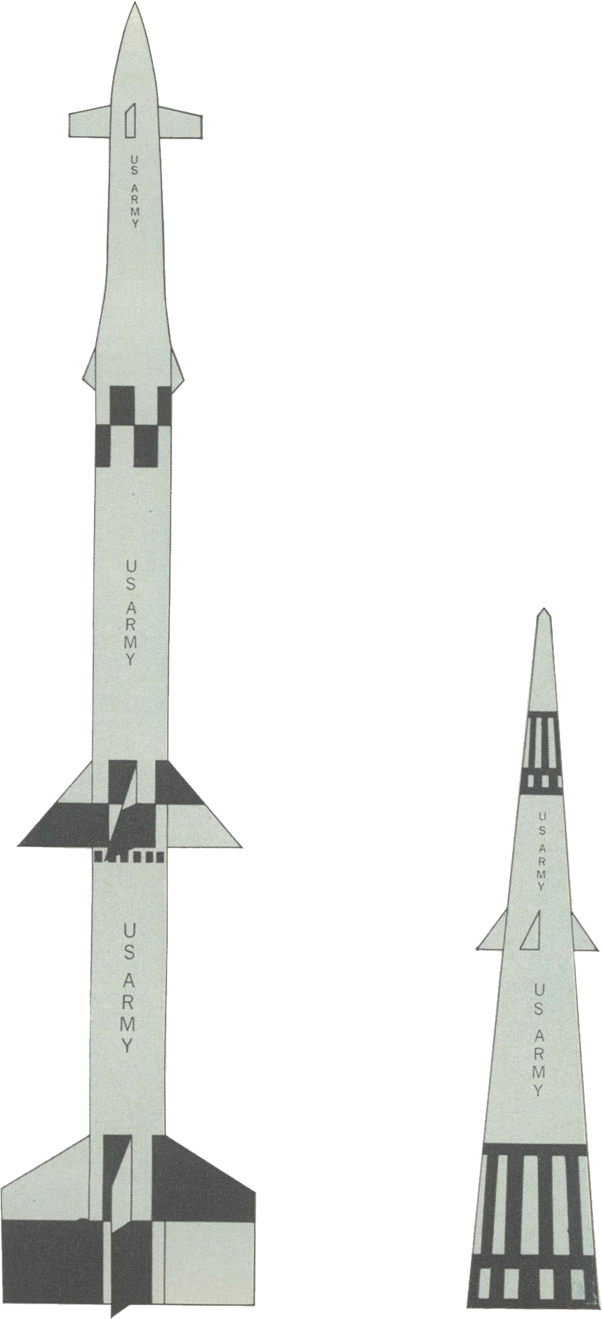
SPARTAN Height: 16.7 meters SPRINT Height: 8.2 meters |
Ballistic-Missile Defense
Radars
|
|
Charles M. Johnson (SM) is the scientific and technical director of the U.S. Army Safeguard System Office. As such, he advises on all scientific matters, technical policies, and major technical decisions that pertain to developing and deploying the Safeguard system. A recipient of the B.E. degree in civil engineering from Vanderbilt University and the Ph.D. in physics from Duke University, he came to the Safeguard system in 1967 from IBM, where he was the manager of the Applied Research Department and was concerned with communications, solid-state devices, lasers and radar systems. Before joining IBM in 1961, Dr. Johnson was director of the Advanced Systems and Microwave Departments at Emerson Research Laboratories, responsible for research and development programs in many areas. From 1956 to 1960, he was manager of the microwave and physics section at Electronic Communications, Inc. Other experience was obtained at the radiation laboratory of Johns Hopkins University, and as a consultant to various corporations. Dr. Johnson has published 27 technical papers on topics ranging from microwave spectroscopy and millimeter-wave techniques to ferrite devices and electronically scanned antennas. A member of the American Physical Society, he is listed in American Men of Science. |
Ballistic-missile defense has been continuously researched in the United States for the past 14 years. The Safeguard system itself is an outgrowth of both the Nike-Zeus system and later ballistic-missile components developed by various government agencies. The classic result of this early work was clear—an ICBM could be intercepted by another missile. Hence, the real controversy concerning the workability of such systems centered around an entirely different problem—the “high-traffic environment”—or how to make tens to hundreds of near-simultaneous intercepts while tracking thousands of targets. This article describes the radars that have led to a solution of this problem, and how such radars operate within the framework of the world's most sophisticated defense system.
Although the Safeguard Ballistic-Missile Defense (BMD) system, its objectives, its major components, and their functions have been described in various news articles during the U.S. Congressional debate over deployment of a BMD system, let me briefly review some of the general features before addressing the specific subject of ballistic-missile defense radars.
First of all, the objectives of the Safeguard system as announced by President Nixon in March 1969 are
To defend our Minuteman missiles against a possible first strike by Soviet Union intercontinental ballistic missiles (ICBMs).
To defend our SAC bombers against a possible Soviet Union submarine-launched ballistic missile (SLBM) threat.
To defend our population against the possible Chinese ICBM threat of the next ten years.
To protect our population from an accidental launch by any nuclear power.
The major components of the Safeguard system are the following (see Fig. 1 for Spartan and Sprint data):
PAR (perimeter acquisition radar)—UHF phased-array radar for long-range search, acquisition, and track of incoming enemy ballistic missiles.
MSR (missile site radar)—the battle management radar. The MSR is primarily a precision target-tracking and missile-guidance radar. It is a high-traffic-capacity phased array that operates in the S-band region. It has less range capability than the PAR but higher resolution.
Spartan—a long-range exoatmospheric interceptor capable of making intercepts at ranges of several hundred kilometers from the launch battery. It carries a high-yield warhead that can kill enemy reentry vehicles (RVs) at a range of several kilometers.
Sprint—a short-range high-performance terminal interceptor. This interceptor has an operating range of several tens of kilometers against enemy RVs. Greater radar tracking precision is required for Sprint intercepts than for Spartan intercepts due to the much smaller Sprint nuclear warhead.
Data-processing system (DPS). Although a data-processing subsystem is an integral part of each of the Safeguard phased-array radars, it is of sufficient fundamental importance to system operation that it is considered a major component. Functions performed include radar control, incoming target selection and tracking, interceptor guidance, message formating, and data reduction for command and control displays and consoles. The Safeguard data processor is configured as a multiprocessor and is denoted as the central logic and control (CLC) system. Several processors with access to a common memory can operate in parallel on several different tracks or on different parts of the same track.
FIGURE 1. Safeguard components.
SPARTAN Height: 16.7 meters SPRINT Height: 8.2 meters |
Fundamentally, the technical prescription for the Safeguard BMD system comprises the following:
Intercept a missile with a missile.
Kill a nuclear weapon with a nuclear weapon.
Establish continuous surveillance of possible threat corridors with phased-array radars.
Sense high-traffic engagement conditions with phased-array radars.
Control radars and interceptors with high-capacity data-processing systems.
Initiate or veto system response via a command chain headed by the President of the U.S.
In addition, the Safeguard system is designed to be
Continuously alert and available for possible threats.
Capable of being exercised at frequent intervals to full radar and data-processing capacity as an integrated multi-site defense system.
Operable while undergoing maintenance.
Capable of being tested on-site for "glitches,” troop readiness and proficiency, and operability.
Although achievement of some of these features can only be measured in full after the Safeguard system is deployed, most have been thoroughly researched, developed, and tested during the years of the Nike-Zeus to Safeguard evolutionary development program.
The development status of the Safeguard system at the present time is as follows:
The Spartan missile is undergoing developmental test firings at Kwajalein Atoll in the Pacific.
The Sprint missile is undergoing developmental test firings at White Sands, N.Mex.
A prototype MSR has been completely constructed at Meck Island (Kwajalein) and is being used to track targets.
A four-processor Safeguard data-processing system has been completely installed at the Meck Island MSR.
A PAR brassboard model is being developed at General Electric.
Tactical software development is under way at the Data Processing Center at Bell Telephone Laboratories, Whippany, NJ.
Under fully projected Safeguard deployment (Fig. 2), a deployment to be made only if the threat requires it, 12 batteries, each consisting of an MSR plus Spartan and Sprint missiles, might be deployed over the continental United States. In addition, a total of seven PARs will be deployed around the perimeter of the country, each PAR being located close by (within about 16 km) an MSR/interceptor battery. All of the MSRs and PARs are interconnected by communications lines and the entire network is controlled from a Ballistic-Missile Defense Center (BMDC) located at Colorado Springs, Colo.
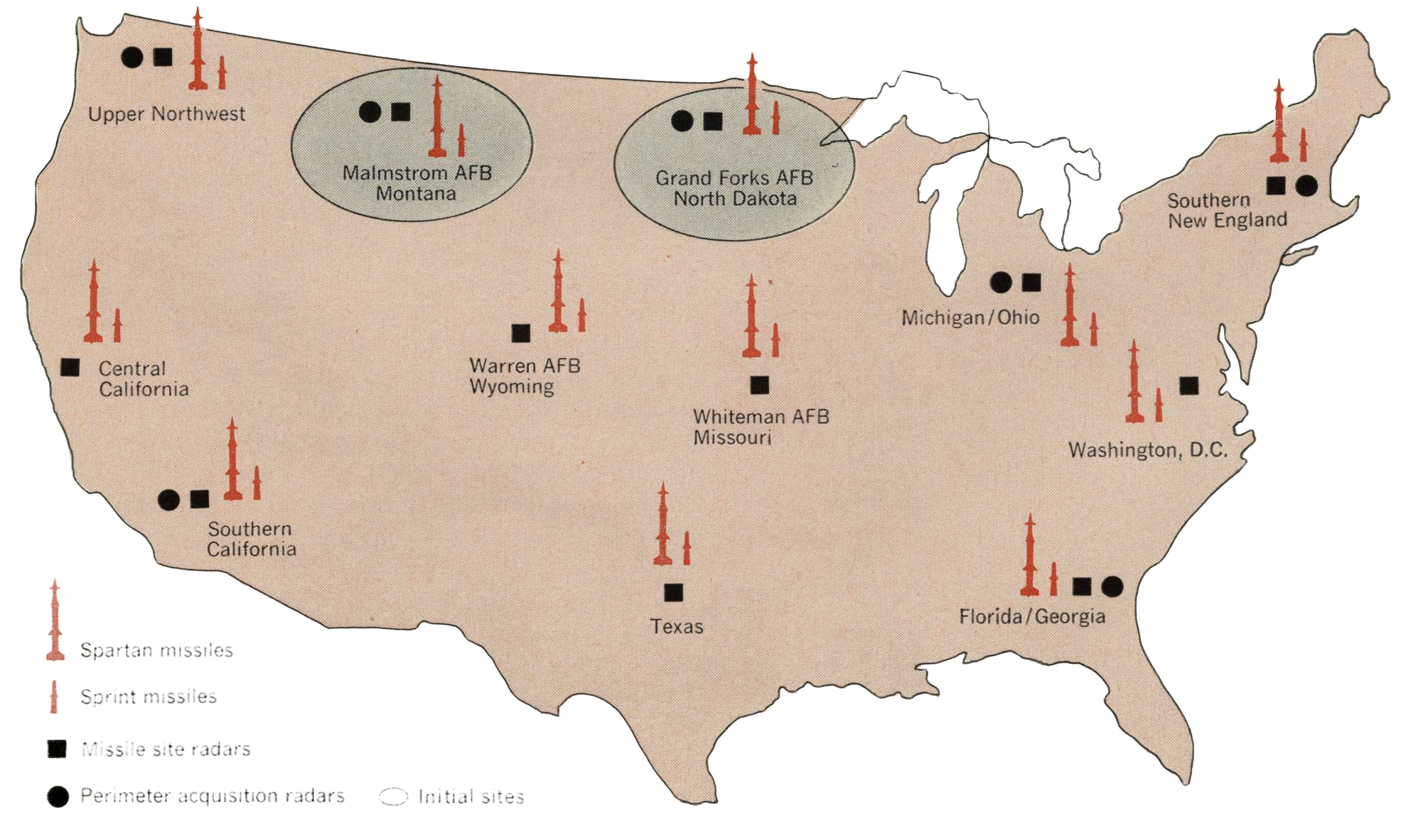
FIGURE 2. Safeguard deployment in the United States |
Under phase 1 of the Safeguard deployment, the only deployment currently requested by the present Administration, only two defense batteries are authorized; both are located at Minuteman Wings, one at Grand Forks, N.Dak., and one at Malmstrom Air Force Base, Mont. Also included in the phase 1 deployment are two PARs located near the MSRs at the defense batteries. The phase 1 deployment will give some protection to our Minuteman force; however, the major purpose of this deployment is to gain experience and work out problems that develop in the manufacture, installation, test, and operation of a ballistic-missile defense entity.
The Safeguard system is the result of both the Nike-Zeus system, proposed for deployment by the Army in 1962, and later ballistic-missile defense components resulting from research sponsored by the Advanced Research Projects Agency (ARPA) and by other Department of Defense and AEC research-and-development programs.
The outstanding result obtained from this eary Nike-Zeus work was proof that an 1CBM could be intercepted by another missile. This capability, along with the fact that one nuclear weapon could be killed by another, is seldom questioned by anyone at this time. Most of the controversy as to whether or not a BMD system will work centers upon problems associated with a “high-traffic environment”—i.e., on problems associated with completing tens to hundreds of near-simultaneous intercepts while at the same time tracking hundreds or perhaps thousands of targets. These high-traffic engagements cannot be linearly extrapolated from what is known about a single engagement. There are many interacting problems such as crossing targets, which complicate radar tracking, and simultaneous intercepts, which cause queueing problems for the data processor. In addition, sizable numbers of nuclear bursts clutter the environment and, in many instances, attenuate the radar signals, thus putting an additional burden on both the sensors and the data-processor subsystems. It was not until phased-array radars were developed that one could realistically conceive of a BMD system coping with such a high-traffic environment.
Two basic defense concepts are involved in the Safeguard BMD system—area defense and terminal defense. Area defense involves the detection and tracking of incoming nuclear-armed reentry vehicles (RVs) with long-range radars (PARs) and the interception of these vehicles with long-range defense missiles (Spartans) while they are still high above the atmosphere. This concept is illustrated in Fig. 3.
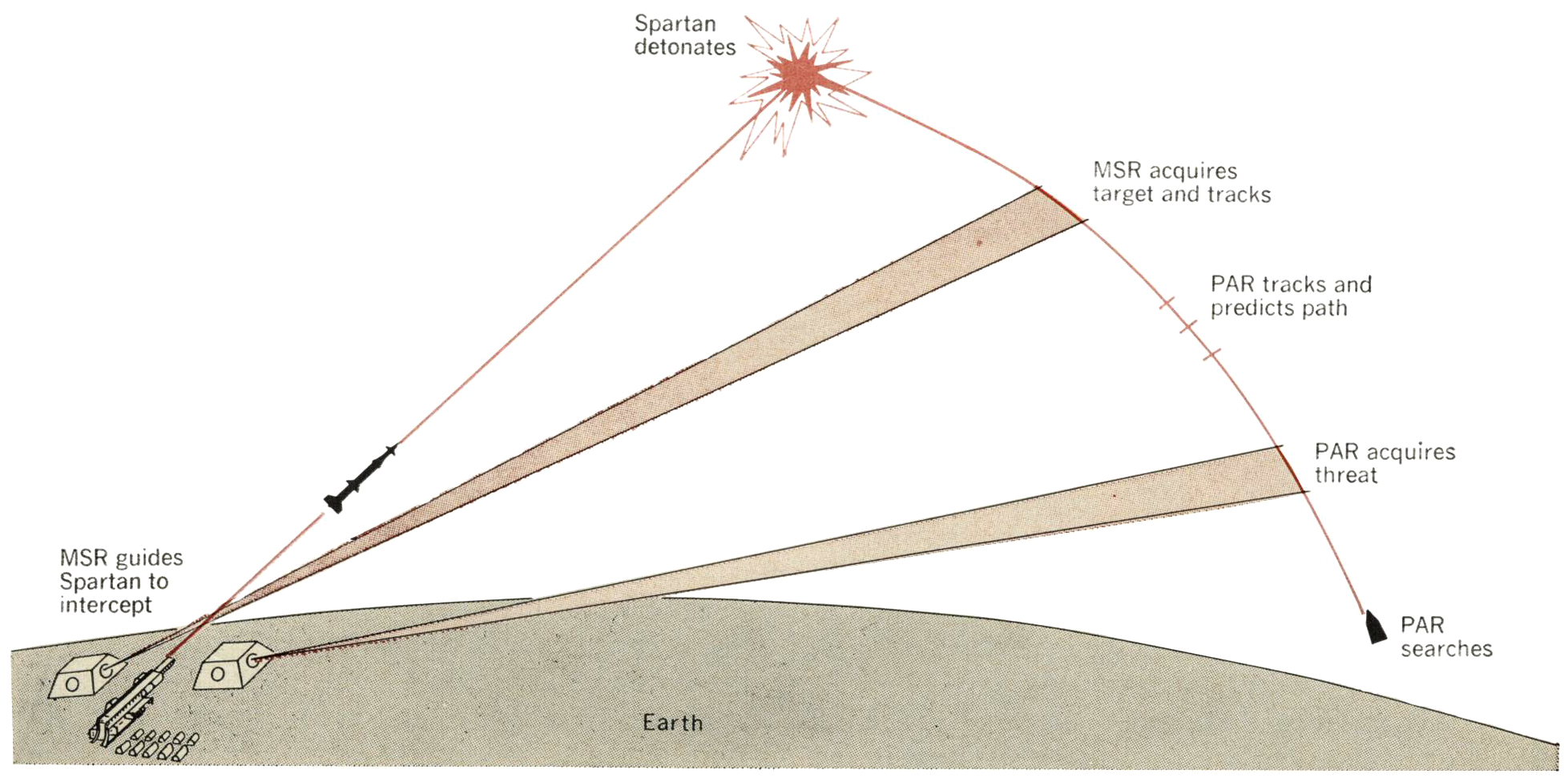
FIGURE 3. Concept of area defense. |
Terminal defense involves the interception of enemy RVs with short-range high-acceleration interceptor missiles (Sprints) after the RVs have reentered the atmosphere and after they have been sorted out by the atmosphere from decoys, chaff, and confusion devices. Terminal defense is conceptually illustrated in Fig. 4.
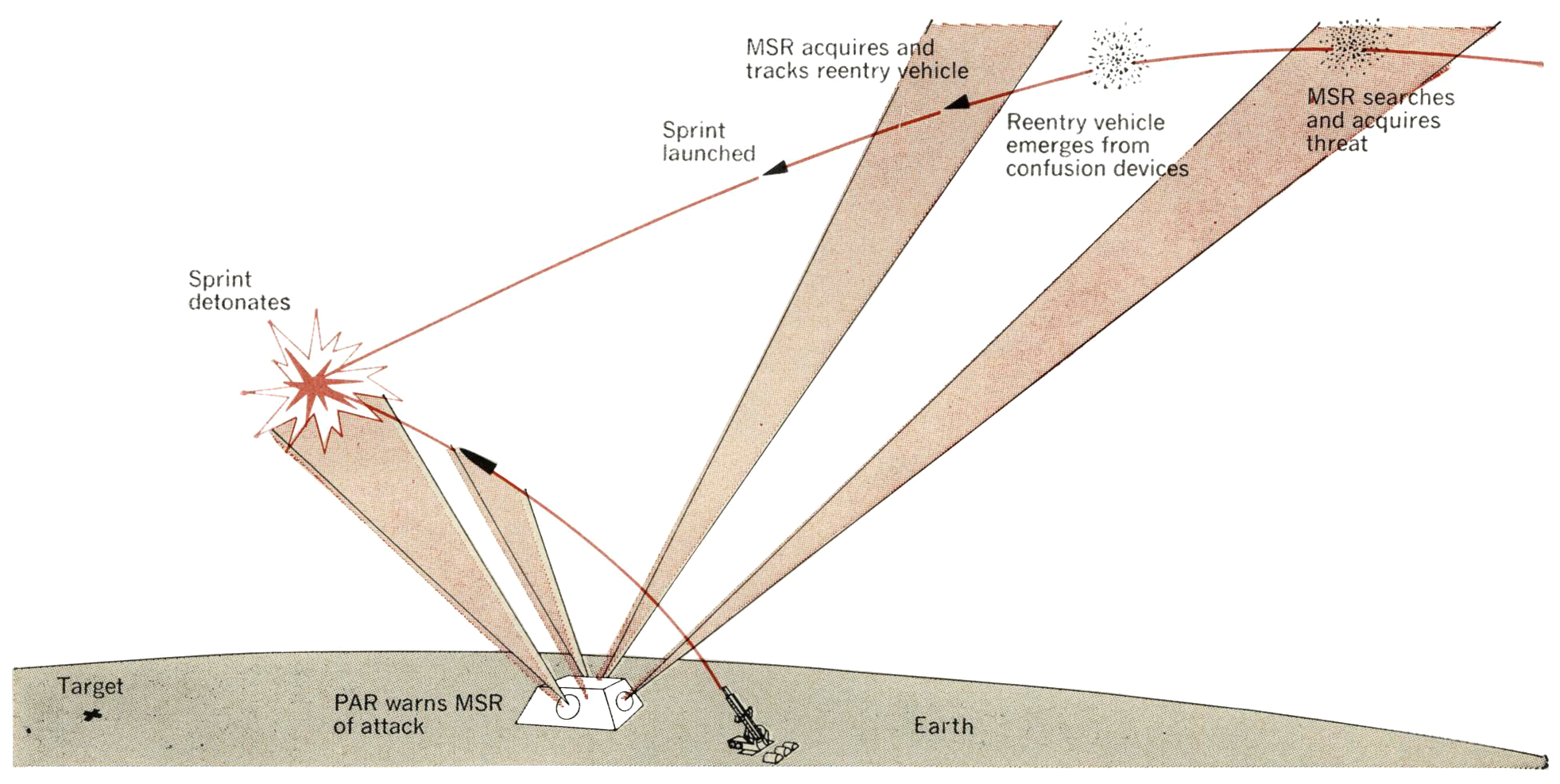
FIGURE 4. Concept of terminal defense. |
Generally , these two types of defense complement each other and provide an in-depth defense that places maximum stress on the offensive force.
The perimeter acquisition radar (PAR) is a UHF phased-array type and is used in the Safeguard system to search for, acquire, and track ICBM and SLBM targets at long range. Figure 5 shows a typical PAR site layout.
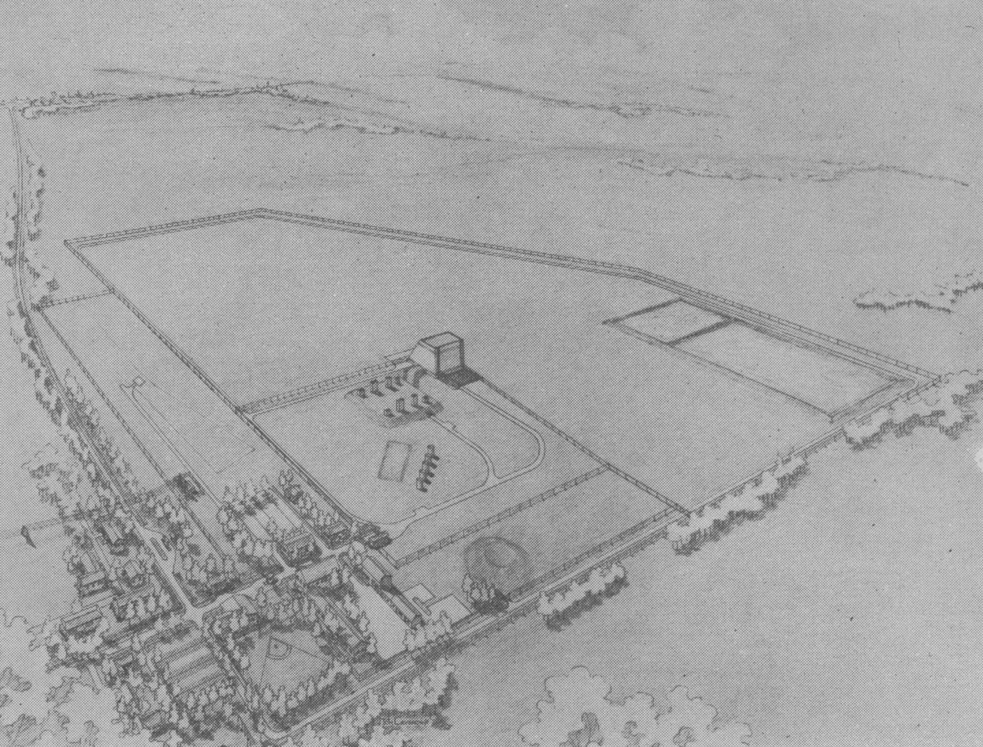
FIGURE 5. Typical Safeguard PAR Site. |
The primary function that determines the PAR power and aperture characteristics is wide-angle search. The requirement to track a great number of objects simultaneously is a strong secondary determinant of these characteristics.
The principal factors that determined frequency selection and modulation-waveform requirements for the PAR were (1) cost of power and aperture versus frequency, (2) radar cross section (RCS) of reentry vehicles versus frequency, and (3) propagation effects in both benign and nuclear environments versus frequency. Secondary factors considered in selecting frequency and modulation waveforms included radio frequency interference (RFI) and available bands for frequency assignment.
The performance of a search radar can be summed up by the following expression:
 \frac{\sigma_\lambda P A}{T} \sim \frac{\Omega}{t} \quad (1) |
where σλ is the target RCS, P the average power of the radar, A the effective receiver-aperture area, T the effective noise temperature, Ω the required solid-angle coverage, and t the time allowed for the radar to search Ω.
The basic point brought out by this expression is that average transmitter power and receiver aperture are important measures of a radar’s search capability, but transmitter gain, or aperture size, is immaterial. Wavelength (or frequency) dependence only enters the relationship indirectly through σλ. For large spherical bodies, σλ is independent of wavelength, but for conical sections nose-on, σ ~ λ2, where λ is the radar wavelength. From this relation, it can be seen that it is generally advantageous to operate a search radar at as low a frequency (long wavelength) as possible so long as the wavelength is similar to but less than target dimension.
If the radar must perform a sizable tracking role, then transmitter gain becomes important. The following expression describes the performance of a tracking radar:
 \text{Track accuracy} \sim \frac{P A^{2} G \sigma_\lambda}{\lambda^{2} T} \quad (2) |
where G is the transmit gain, λ is the radar wavelength, and σλ is again the RCS of the target. The wavelength dependence strongly favors short-wavelength (high-frequency) operation if the target RCS is independent of frequency. However, for conical sections where σ ~ λ2, the wavelength dependence drops out of Eq. (2).
The PAR design was originally conceived as a VHF phased array with two apertures, one for transmit and one for receive. In this original design, the receive aperture was about 30.5 meters in diameter, but the transmit aperture was much smaller. The PAR is now being developed in the UHF region and only one aperture, common for both transmit and receive, is used.
Briefly, the reasons for these changes are as follows. The PAR searches for, and tracks, exoatmospheric ICBM targets. The radar beam must penetrate the ionosphere and, consequently, it is subject to the refractive and attenuative effects of both natural ionization phenomenons, such as aurora, and nuclear-induced ionization phenomenons, such as beta blackout. Generally speaking, the intensity of these high-altitude ionization effects decreases with v2, where v is the radar operating frequency. Thus, the shift from VHF to UHF significantly reduces the effects of these ionization phenomenons on PAR performance.
The switch to a single aperture occurred because of the increased track capacity that could be achieved with a larger transmit aperture, and the cost reduction that could be achieved from the smaller building resulting from combining both the transmit and receive functions into one aperture.
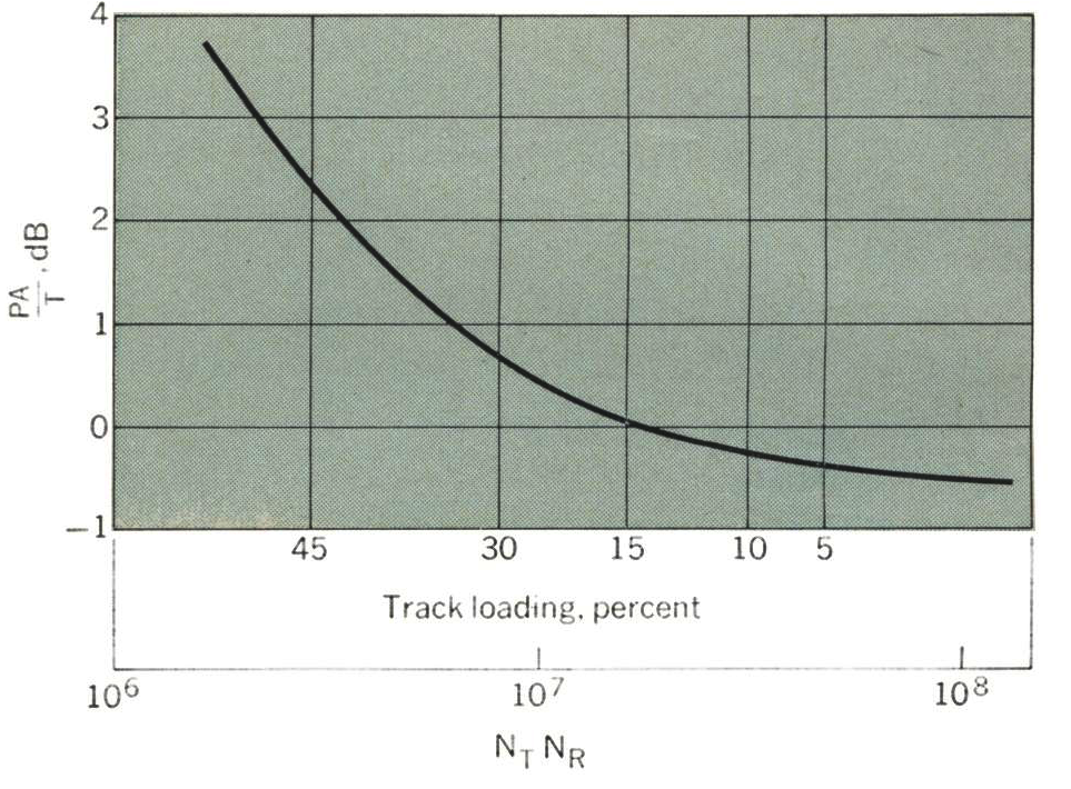
FIGURE 6. Power-aperture/temperature requirements for PAR. |
Figure 6 displays the relative cost in PA/T of providing for the PAR track load as a function of NTNR, where NT is the number of transmit elements and NR is the number of receive elements. Thus, the track requirement can easily dominate the design of PAR-like radar when the transmit aperture is small compared with the receive aperture.
With the foregoing general system considerations established for the PAR (and I must apologize and plead classification restraints for being so qualitative and skimpy in covering these system aspects), let’s take a look at how we arrived at the detailed PAR design. First of all, at the time of the last major transient in the PAR design, namely, in early 1968, several phased-array radar approaches had been developed and some actually implemented, and these were available for us to consider.
The principal approaches included
1. FPS-85 radar. This system utilized low-level heterodyne steering for the transmitter elements and a high-level transmitter output tube at each radiating element. Separate transmit and receive apertures were used. A significant advantage of this scheme is the relatively low cost of the low-level transmitter phasing system. A disadvantage is the relatively high cost of using a complete transmitter chain per element (if full PAR bandwidth and power requirements were to be met by this design).
2. Space-fed arrays. In this case, a single or a few high-power transmitter tubes are used to feed a phased-array antenna from a focal point behind the array. Correspondingly, receive horns are used in this focal area behind the array to detect the return signal. The use of a single aperture forces the system to use high-power phase shifters for at least the portion of the array illuminated by the transmitter. The major advantages of this design are the simplicity of the antenna feed and the relatively low cost of a few ultrahigh-power transmitter tubes. However, these transmitter tubes must be designed for exceptionally high reliability in order to match the high inherent availability/reliability of the phased-array radar. Also, these ultrahigh-power transmitter tubes require ultrahigh-voltage power supplies and these supplies are generally more difficult to engineer and they occupy larger amounts of premium radar building space than is the case with lower-voltage supplies.
3. Corporate-fed arrays. In this category, a fairly broad range of designs is possible. The choices include single-aperture and double-aperture configurations, high-level or low-level transmitter steering, and a transmitter tube per radiating element or one transmitter tube for many radiating elements. Generally, in the phased-array category, endless arguments can be generated as to the optimum subarraying ratio, transmitter number and division, and receiver number and technology.
4. Solid-state arrays. This category is similar to approach 3 except for the substitution of a solid-state transmitter output stage for a tube transmitter output stage.
Designs based on the foregoing techniques were generated that would meet the PAR system requirements. Each of these designs was costed and compared. The general cost trends were the following:
1. Required PA/T reduces as NTNR increases.
2. RF power-generation costs tend to be lower as power per tube increases.
3. Losses increase as power per tube increases.
4. Prime power costs depend on efficiency.
5. Need for redundancy increases as the number of tubes decreases.
In addition to these directly related radar cost factors, hardened building costs, which amount to a major fraction of the total radar cost, are a function of the radar design. In the case of the PAR, building size is controlled primarily by aperture requirements.
It was concluded from this cost comparison that a corporate-fed common-aperture design with a few hundred high-level transmitters power-divided to the several thousand antenna elements was the most economical approach for realizing the PAR requirements; however, it should be stated that the total cost swing over the entire ensemble of designs amounted to a factor of less than 30 percent.
A schematic design of the PAR phasing network that is currently under development is shown in Fig. 7.
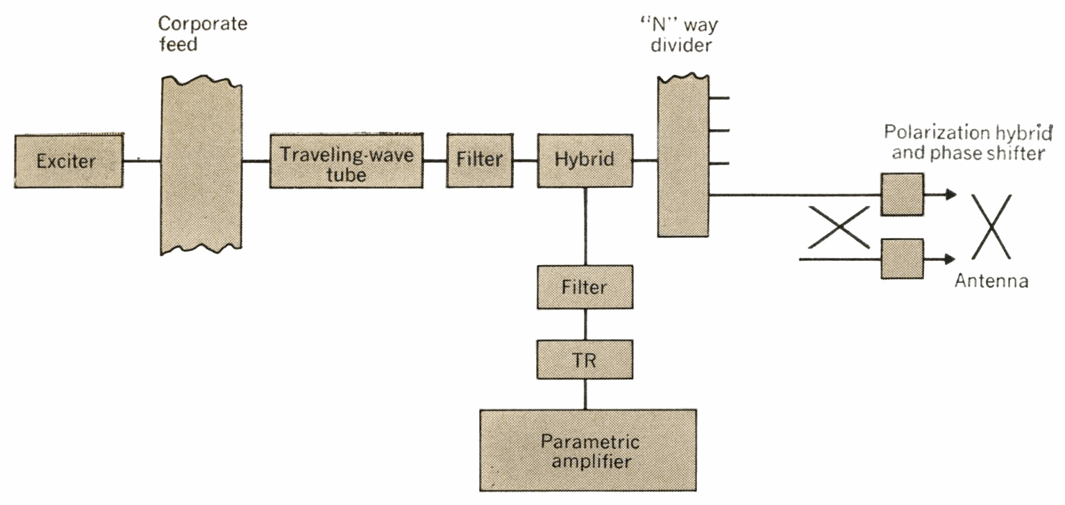
FIGURE 7. Schematic design of PAR. |
It is simply a conventional corporate-fed array with traveling wave-tube output stages for the transmitter and parametric amplifiers for the receivers. The antenna array consists of a number of subarrays arranged to minimize perturbations caused by transmitter or receiver outages. The phase shifters are 4-bit diode type; orthogonal steering is used and a special-purpose beam-steering computer controls the array of phase shifters. The PAR central processor (CLC) furnishes the sine space coordinates to which the beam is steered.
The PAR utilizes a number of receivers matched to the various functions. The search receiver consists of multiple channels that permit simultaneous generation of multiple receiver beams. The track receivers utilize monopulse tracking to achieve accuracies that are a small fraction of a beam width.
The PAR, unlike some other Safeguard components, must operate continuously—monitoring all space objects that come within its field of view. By the time the radar is in place, this load will amount to several thousand objects per day. Consequently, the PAR transmitters and receivers and their supporting equipment must be sufficiently redundant to provide virtually 100 percent availability.
Missile site radar is primarily a precision target-tracking and interceptor-guidance radar and is optimized to operate in a high-traffic environment (see Fig. 8).
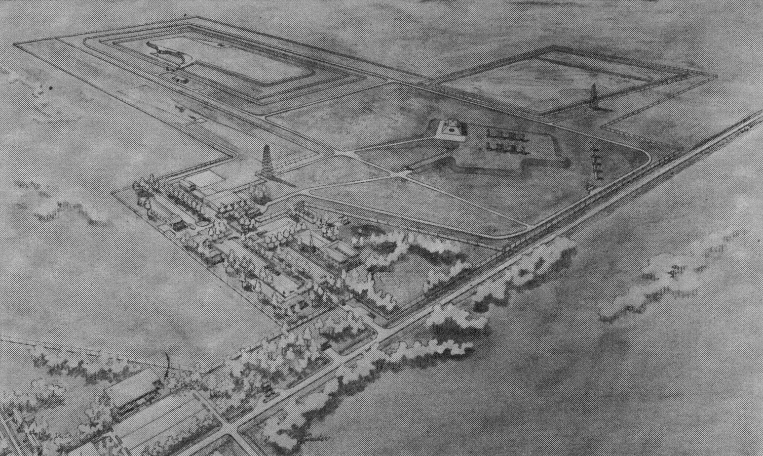
FIGURE 8. Typical Safeguard MSR site. |
Secondarily, the MSR is also capable of autonomous search and target acquisition. It operates in the S-band region and has a range capability of several hundred kilometers against typical RVs. The MSR is of phased-array design with a 4.1-meter-diameter aperture. This single aperture serves for both transmitting and receiving. The MSR is generally configured as a four-faced radar to provide complete 360-degree azimuthal coverage.
The MSR building has about the same floor space area as the PAR but has only about 1/100 the antenna aperture area. Perhaps the only conclusion that can be drawn from this is that radar building size is not a rapid function of antenna aperture.
The basic design of the MSR was accomplished approximately five years ago and a prototype model is now being operated at Meck Island, a part of the Kwajalein test site.
Figure 9 depicts the MSR antenna array and feed.
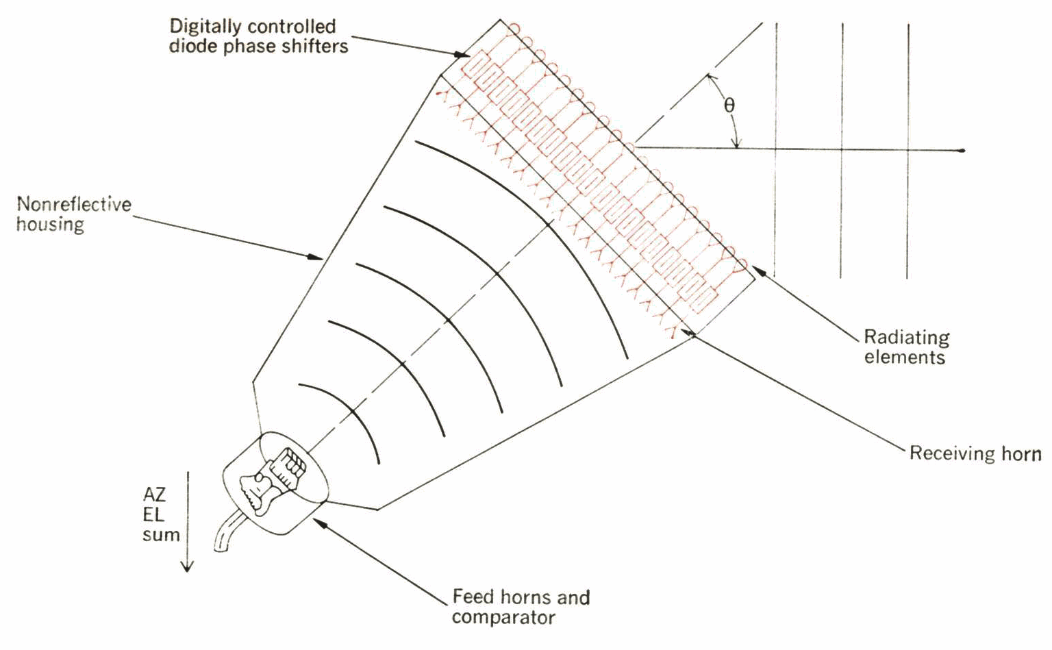
FIGURE 9. Missile-site radar antenna array. |
The antenna is a space-fed phased-array type with separate transmitting and receiving feed horns located at the rear of an anechoic chamber. The antenna thus acts as a focusing lens for the focal point feed. The phase shifters located in the antenna face serve both to collimate the microwave energy from the feed and to steer the resulting beam to the desired spatial direction. The diode phase-shifter cartridge that makes up the array is drawn in Fig. 10.
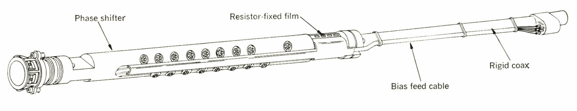
FIGURE 10. Phase-shifter cartridge. |
The MSR functional block diagram can be seen in Fig. 11.
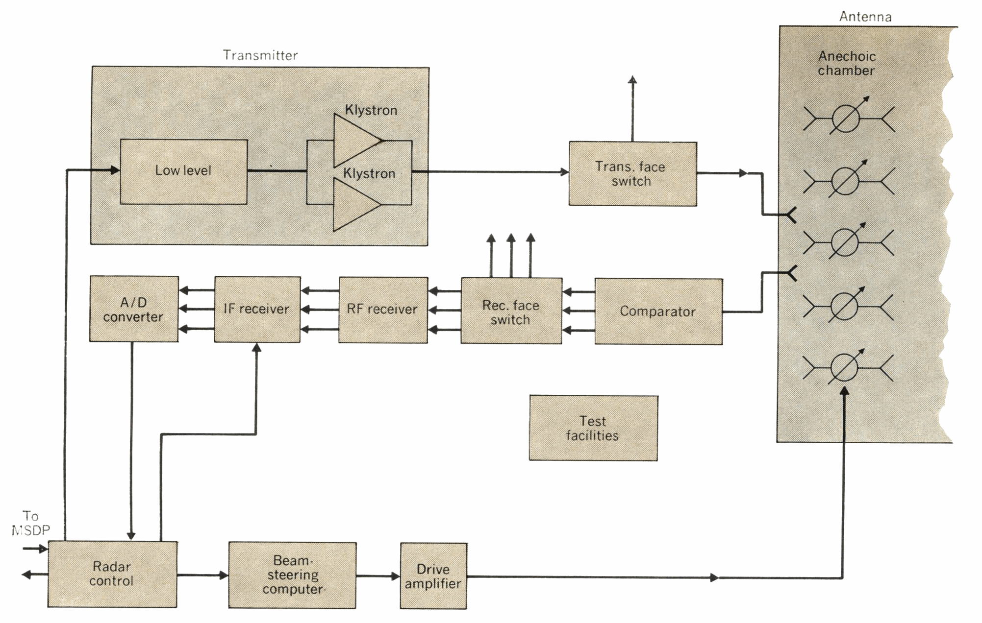
FIGURE 11. MSR functional block diagram. |
A special-purpose computer with appropriate drive amplifiers controls the array phase shifters. The MSR central data processor furnishes sine space coordinates to the beam-steering computer for the position to which the beam is to be steered. The beam-steering computer then solves the following orthogonal equation in order to determine the phase shift θmn that is required for each element:

\theta_{mn} = \left[ m \alpha_1 + n \beta_1 + G_{mn} + \left( m \gamma_x^2 + n \gamma_y^2 \right) \right] (1 - \nu) \quad (3) |
where Gmn equals the constants that take into account manufacturing tolerances, (1 — v) is the frequency correction term, and

\alpha_{1} = \frac{2 \pi dx}{\lambda} \sin \alpha \quad \beta_{1} = \frac{2 \pi dy}{\lambda} \sin \beta |
where dx is the physical separation between the element columns, and dy is the physical separation between the element rows.
The MSR transmitter consists of redundant, high-power klystrons capable of generating high peak power in a variety of pulse widths. The transmitter also produces exceptionally large amounts of average power, thus permitting the MSR to perform its multifunction roles. Because of its completely redundant design, it is possible to perform maintenance on the transmitter while it is “on-line.”
The transmitter output tube is shown in Fig. 12.
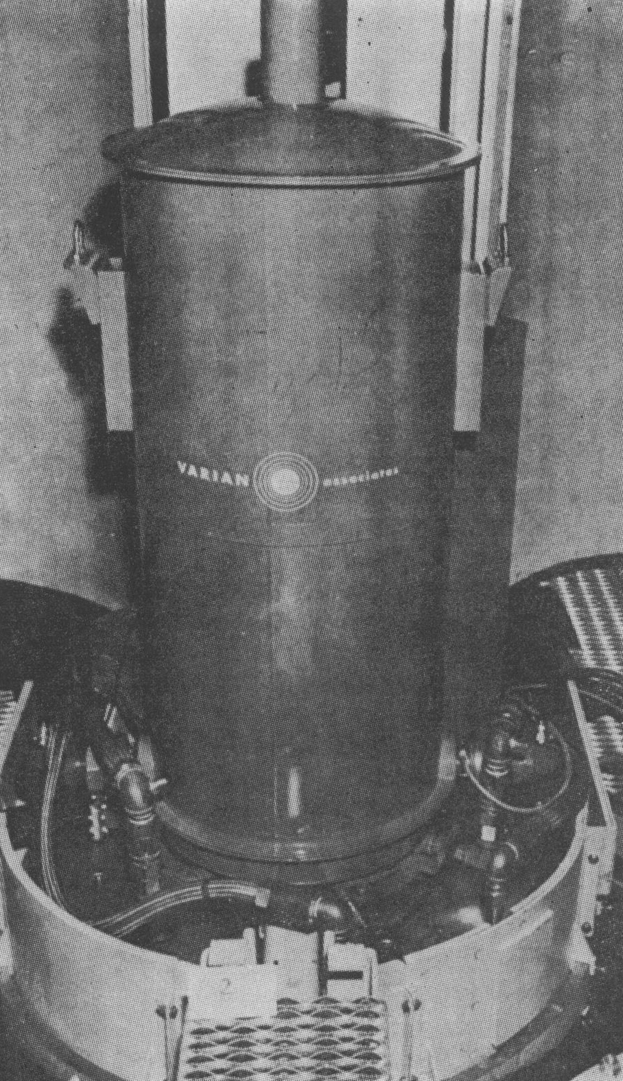
FIGURE 12. Klystron in solenoid of MSR transmitter. |
The MSR receiver uses redundant channels to achieve virtually 100 percent availability. There is a set of receivers matched to each of the possible transmitted waveforms. These receivers have a common RF section featuring a cooled parametric amplifier. The MSR has both search and track receivers. The track receiver utilizes amplitude monopulse to determine accurately the position of targets to within fractions of a beam width. All receivers can be switched to handle inputs from the different array faces.
The data-processing system (DPS) hardware for the PAR, MSR, and BMDC sites uses common hardware modules, or racks, interconnected as a multiprocessing system. The central logic and control unit (CLC), which is the heart of the system, uses at least two each of the following units: processor units, program storage units (each containing two 8K 64-bit word modules), operand storage units (each containing 16K 64-bit words), input/ output controllers, and timing and status units. Additional processor units and storage units may be added as required. Multiprocessing, in addition to providing assurance of large throughputs by adding more processors, has the further advantages of modularity, permitting the most economical size of DPS installation at each site as well as providing, through redundant units, a high degree of fail-safe operation.
The following examples will give a general feel of how this data-processing hardware can handle the BMD problem:
1. When the PAR makes a track measurement on an object, it uses this measurement to update and refine the predicted trajectory of the object. Each such calculation requires very many operations in the data processor. However, the data-processor speed is such that a single processor unit can perform the entire calculation in about 1 or 2 milliseconds. Because the radars were designed to give high-accuracy measurements on each track pulse, only of the order of 100 pulse hits per target are needed, and these can be spread over several minutes of the target’s trajectory. Therefore, the average time required of a processor is less than a millisecond per object per second. Thus, a single processor unit may perform trajectory predictions for over 1000 objects simultaneously. Since a massive attack would last for minutes and not all objects would appear simultaneously, a processor unit would build up to this rate. As it finished with a particular track, it would drop the object and start on a new object. Thus if, just as an example, an attack lasted for 30 minutes with several hundred objects entering coverage per minute, a processor unit could handle several thousand objects over the duration of the attack.
2. Spartan and Sprint guidance calculations take longer time per calculation and are made at a higher average rate. However, the number of defensive missiles that must be in guidance simultaneously from one MSR is small compared with the total objects (reentry vehicle plus junk) a PAR must handle.
These two examples are discussed since, in the peak-load situation, they are the most demanding of data-processor time at the two different sites. The actual number of processor units required for each defense site is selected based on the postulated threat. Additional processor units are added to handle all of the other functions required to support these basic functions and to supply the necessary number of spare processors to meet availability requirements.
The software weapons process structure is composed of tactical routines plus radar and computer tests, as well as maintenance, diagnostic, and operating system routines. These run on a real-time basis with fixed operating deadlines tied to the radar major cycles.
Software facilities based upon third-generation hardware architecture include base-register addressing, doublelevel indexing, indirect addressing, data editing, and registers for internal central-processor-unit (CPU) operations. The software structure is broken down into tasks, which are in turn controlled through a task-list table. Task precedence is controlled through conditional enablement tables, and run priority is controlled through position in an absolute enablement table.
Safeguard hardware and software are both representative of large-scale computer systems of today. Multiprocessors have been used in several data-processing systems as the logical way to provide large data-processing throughputs when uniprocessors with adequate capacity are not available.
The software for the Safeguard system is a complex real-time process but, again, these functions have been carried out before. Except for peak-tracking requirements, the Air Force FPS-85 phased-array radar at Eglin Air Force Base in Florida, which is controlled by a duplex IBM MOD-65 installation, performs tasks quite similar to those required of the PAR DPS.
Although several areas in phased-array technology remain where additional development could lead to significantly improved performance, phased arrays have now reached a state of reasonable technical maturity. Without doubt they constitute one of the major technical breakthroughs leading to effective ballistic-missile defense; but they are very expensive. The most important area to be addressed immediately is believed to be that of reducing the cost of complete phased-array radars. “Complete” means the building, power plant, installation, and testing as well as the electronic portions.
At the present time, our PARs and MSRs are estimated to cost between $150 million and $200 million each when all costs, from site activation to final check-out as an operational system, are included (investment cost). The cost for major parts of these radars is listed in Table I.
I. Safeguard radar cost breakdown |
|
|
Category |
Percent of Investment Cost |
|
Radar electronic components |
25 |
|
Data processor |
12 |
|
Installation and test |
11 |
|
Spare |
5 |
|
Other site equipment |
5 |
|
Radar building |
20 |
|
Power plant and power equipment |
15 |
|
Support facilities, real estate, and design |
7 |
|
|
100 |
In addition to the costs that have been designated as investment costs, there is an operating and maintenance cost for these radars that amounts to about 5 percent of the initial investment per year.
Let me hasten to add that as expensive as these radars appear, they are still much cheaper than the corresponding number of dish radars required to handle comparable assumed traffic in a similar defense role.
The universal feature that comes to mind when one talks of future BMD radars, indeed, future phased arrays in general, is the desirability of all-solid-state design. Specifically, this development refers to the high-power transmitter output stages. Virtually all other parts of phased-array electronics are already solid state. Such widespread desire for this development is somewhat surprising when one considers the increased difficulty in radar operation caused by the characteristics of solid-state microwave sources, usually transistors. These difficulties include the following:
1. Complexities in radar signal and data processing are caused by the necessity to utilize the long-pulse, high-duty-cycle property of transistors if good efficiency is to be realized.
2. Special problems in prime-power conversion and distribution arise as a result of the requirement to furnish low voltage and high current to the transistor collectors.
3. Phased-array designs based on moderate power transistors tend toward use of larger numbers of radiating elements to achieve required system power levels. The resulting narrower beam, coupled with a high duty cycle, creates a need for more beam forming and greater steering ability than is usually required in a phased array using tubes. In addition, large apertures tend to make structural hardening more difficult.
Offsetting these technical difficulties and complexities is the solid-state promise of much simpler maintenance procedures and maintenance costs. If the long-life claims made by the semiconductor people are valid, then it is conceivable that phased-array radars can be built that require only periodic maintenance, or perhaps even no maintenance at all, for the life of the system. Such a radar could be unattended, and many such radars could be controlled from remote central sites. The availability of such components would certainly have a major impact on ballistic-missile defense concepts.