|
|
Cold War Geodesy
|
|
|
Cold War Geodesy
|
General NotesWork on the A-135 program began in late 1968; with a two tier system similar to the US SPARTAN/SPRINT system adopted by late 1969. On 10 June 1971, USSR Council of Ministers Resolution No. 376-119 was issued, authorizing the creation of the A-135 missile defense system, to consist of two systems: "Амур" (Amur) Long Range Interception Firing Complex "Амур-П" (Amur-P) – Prototype Long Range Interception Firing Complex Plans called for three Amur complexes near Moscow at distances from 600 to 800 km, backed up by three S-225 [С-225] universal air defense system complexes. In December 1971, the preliminary design of the A-135/Amur system was completed and OKB Fakel was selected as the main contractor for development of the long range two-stage exoatmospheric interceptor A-925/51T6. Following the signing of the ABM Treaty in June 1972, the Amur/A-135 system was redesigned to accommodate all assets within an area of 100 km in the Moscow region. The S-225 complexes were removed from the system, but the short-range high speed interceptor missile PRS-1/5Ya26 [ПРС-1/5Я26] developed for the S-225 was selected as the short-range atmospheric tier for A-135, continuing development under a new GRAU Index [53T6]. The redesigned A-135 system was presented to the Ministry of Defense in 1973 and approved by the end of 1973. The system was redesigned yet again following the signing of the 1974 ABM Treaty Protocol which reduced each side's ABM deployment areas from two [National Capital + ICBM field] to just one site per country. This redesign lasted 1975-1976; while testing of missile prototypes began in 1973 and continued into the 1980s:
Deliveries of service 51T6/53T6 missiles began to units in 1990, with the system accepted into trial operation in December 1990, with trial combat duty beginning on 11 February 1991. At the time of trial duty, the total compute in the DON-2N's KVP-135 command post was about 1000 MIPS divided amongst four x 10-CPU Elbrus-2 MVK computers, each running at 250 MIPS each. (One source claims only 125 MIPS, but this may be for the early 1987 prototypes at Shary Shagan, not the later models in Moscow). When the Don-2NP (Дон-2НП) (HORSE LEG) prototype at Sary Shagan [46.00306, 73.64926] began operation in the mid to late 1970s, it was with the earlier Elbrus-1 computers, which provided only 15 MIPS per computer. The Soviet computing industry took from 1979 to 1986 to deliver an operational Elbrus-1; and the Elbrus-2 itself, which saw first prototypes in 1984 and limited production in 1987 – required a redesign in 1992 to make it reliable. Experimental work began at the Amur-P test complex during 1989-1990 to reduce the lower boundary and increase the outer boundary of the target engagement zone for the 53T6 missile; along with the Samolet-M («Самолет-М») program, intended to equip the 53T6 with a non-nuclear warhead. Formal combat alert began on 1 December 1995, with it being officially accepted into service in 1996. In 2003, the 51T6 missiles were decommissioned, leaving only the 53T6s. In the early 2000s, the Elbrus-2 computer network in the KVP-135 [КВП-135] Command Post was replaced with a local network using Elbrus-90 micro servers. Currently the 1st Moscow Order of Lenin Special Purpose Air and Missile Defense Army (1-я Московская ордена Ленина армия противовоздушной и противоракетной обороны особого назначения) operates the A-135 complex through the 9th Anti-Ballistic Missile Defense Division (9-ой Дивизией ПРО). Known specifications of the Moscow A-135 complex are: [LINK TO ARCHIVED RUSSIAN LANGUAGE COMMENTARY ON A-135] 5Н20 [5N20] DON-2N [Дон-2Н] (PILL BOX) Radar:Construction of the radar itself began in 1978; with the radar bunker complete by 1980, allowing installation of internal equipment which was largely complete by around 1983-84. The development of the Don-2N radar required:
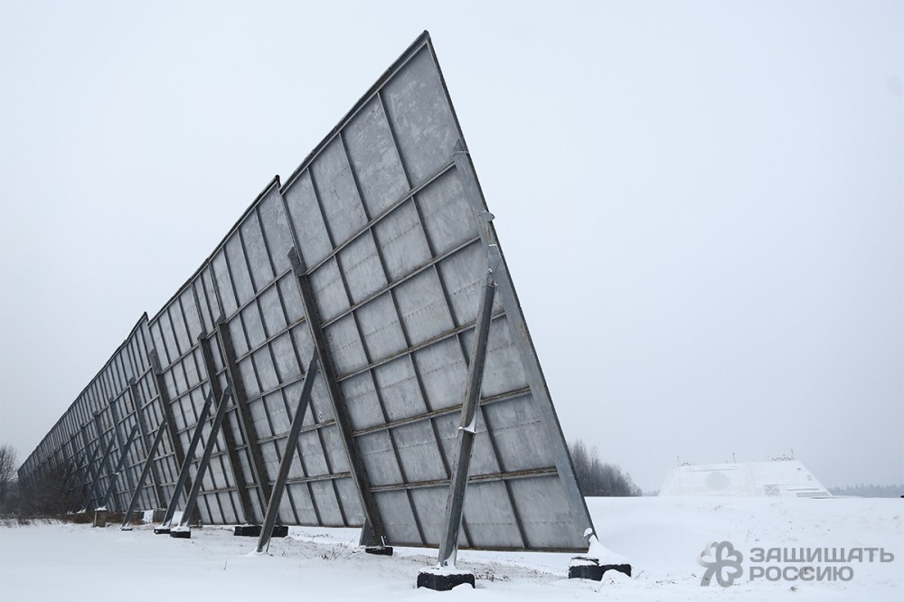
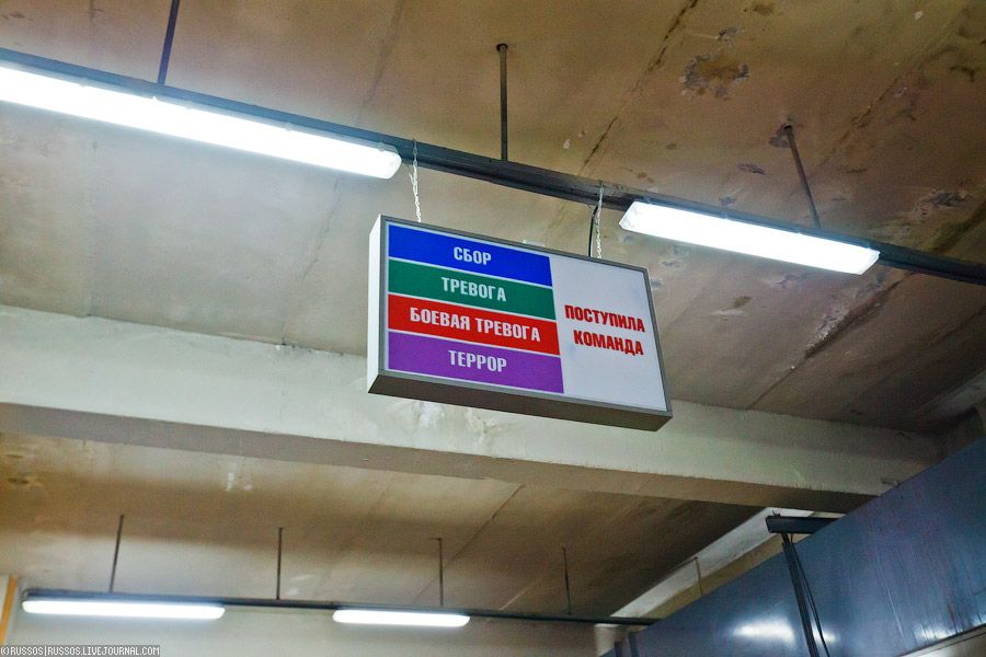
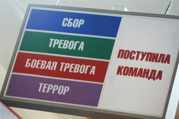
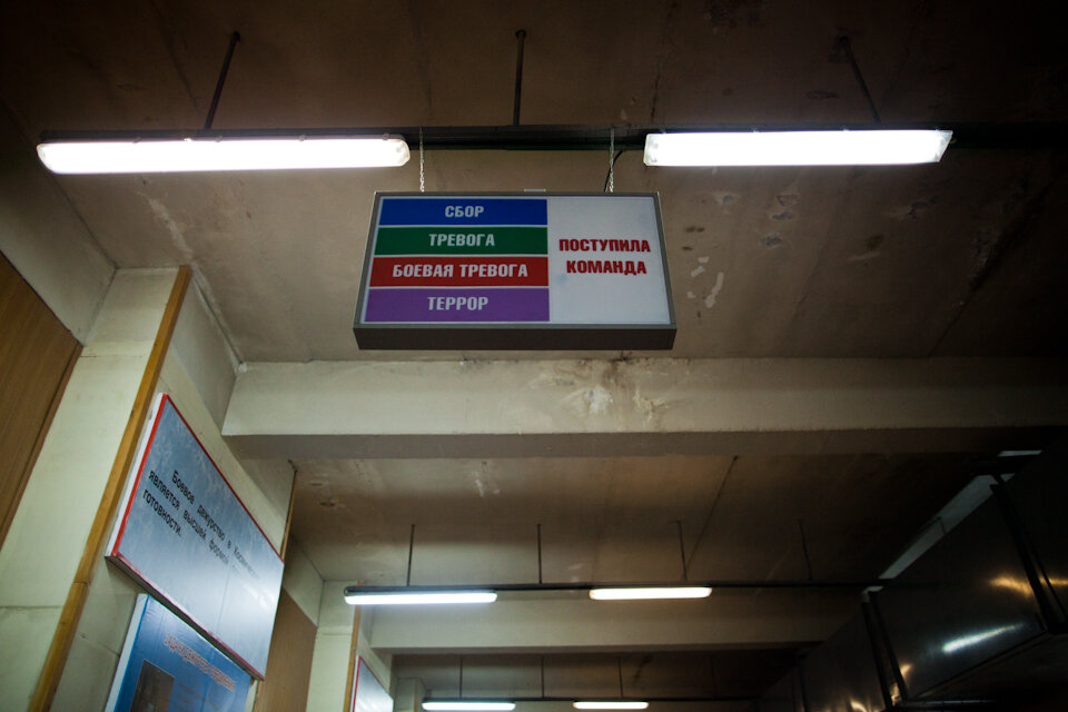
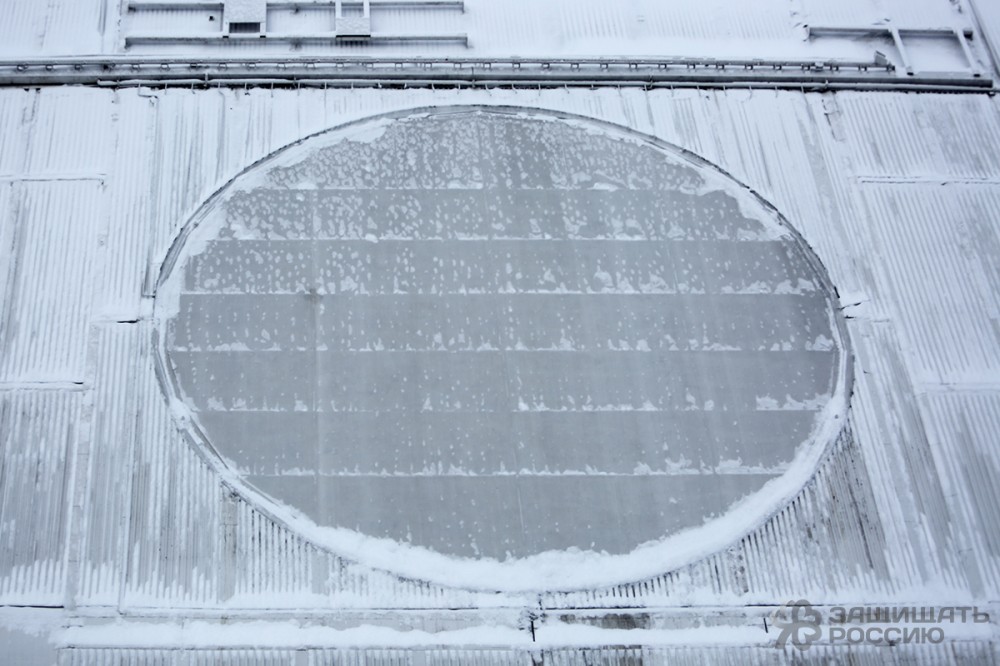
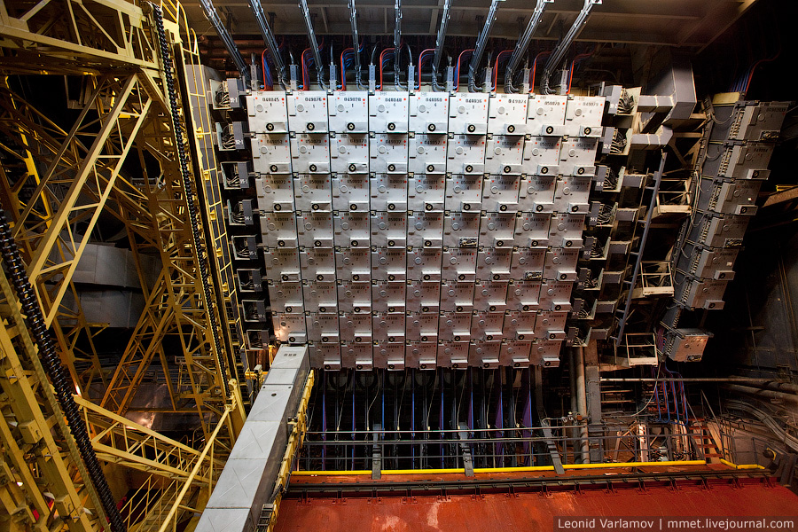
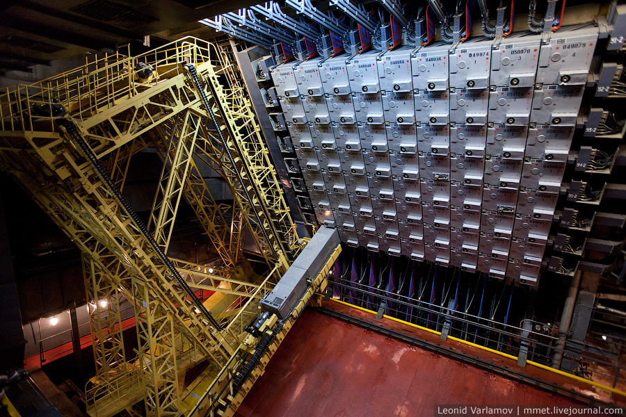
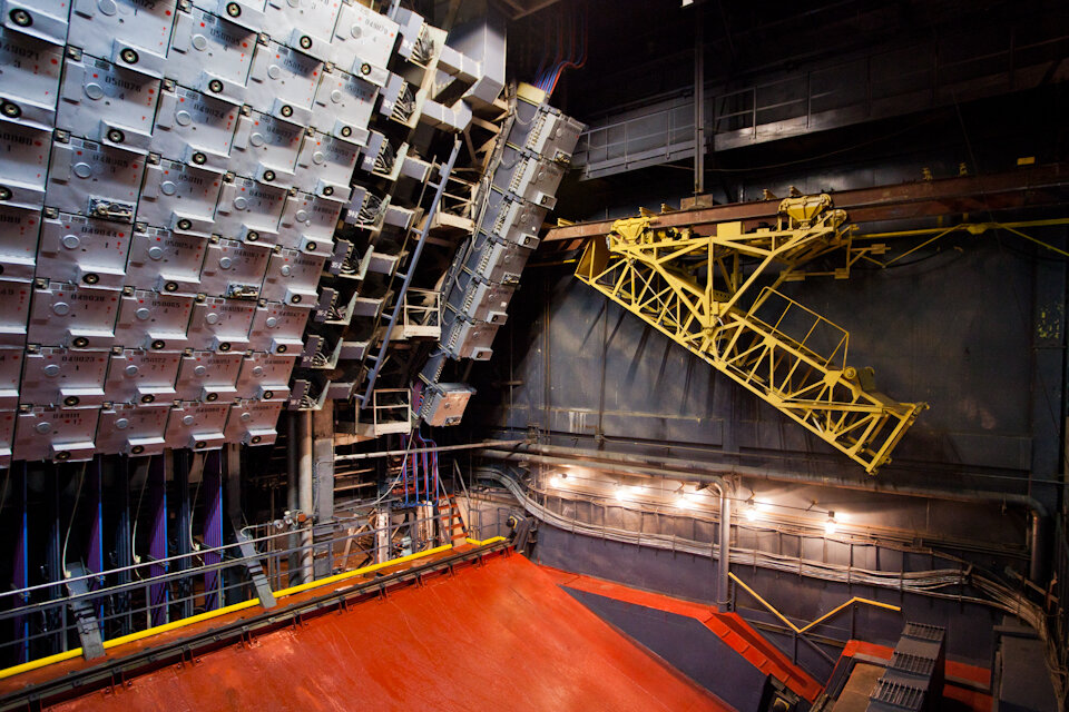
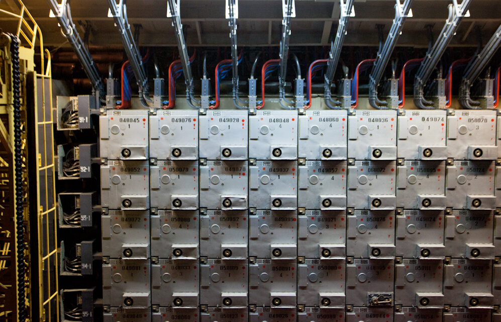
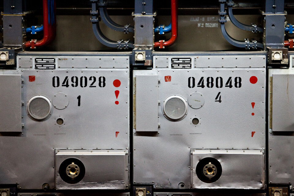
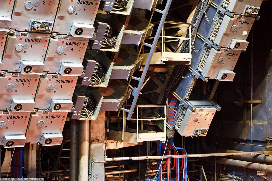
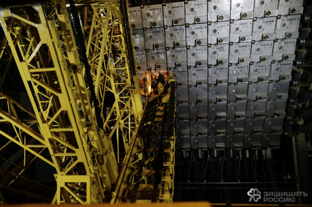
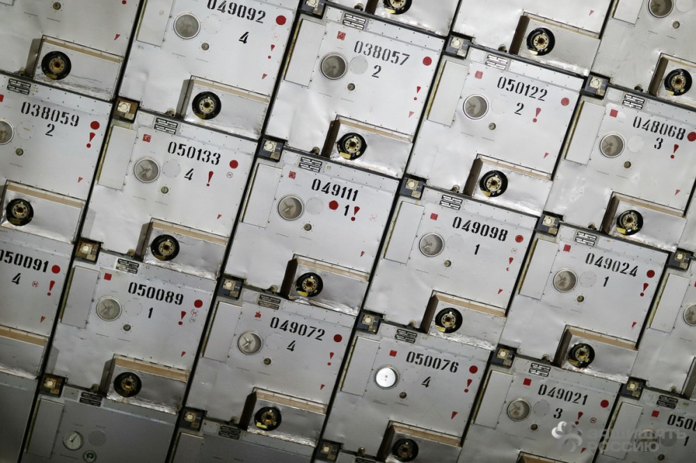
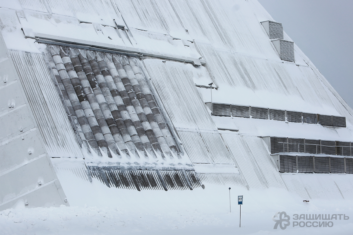
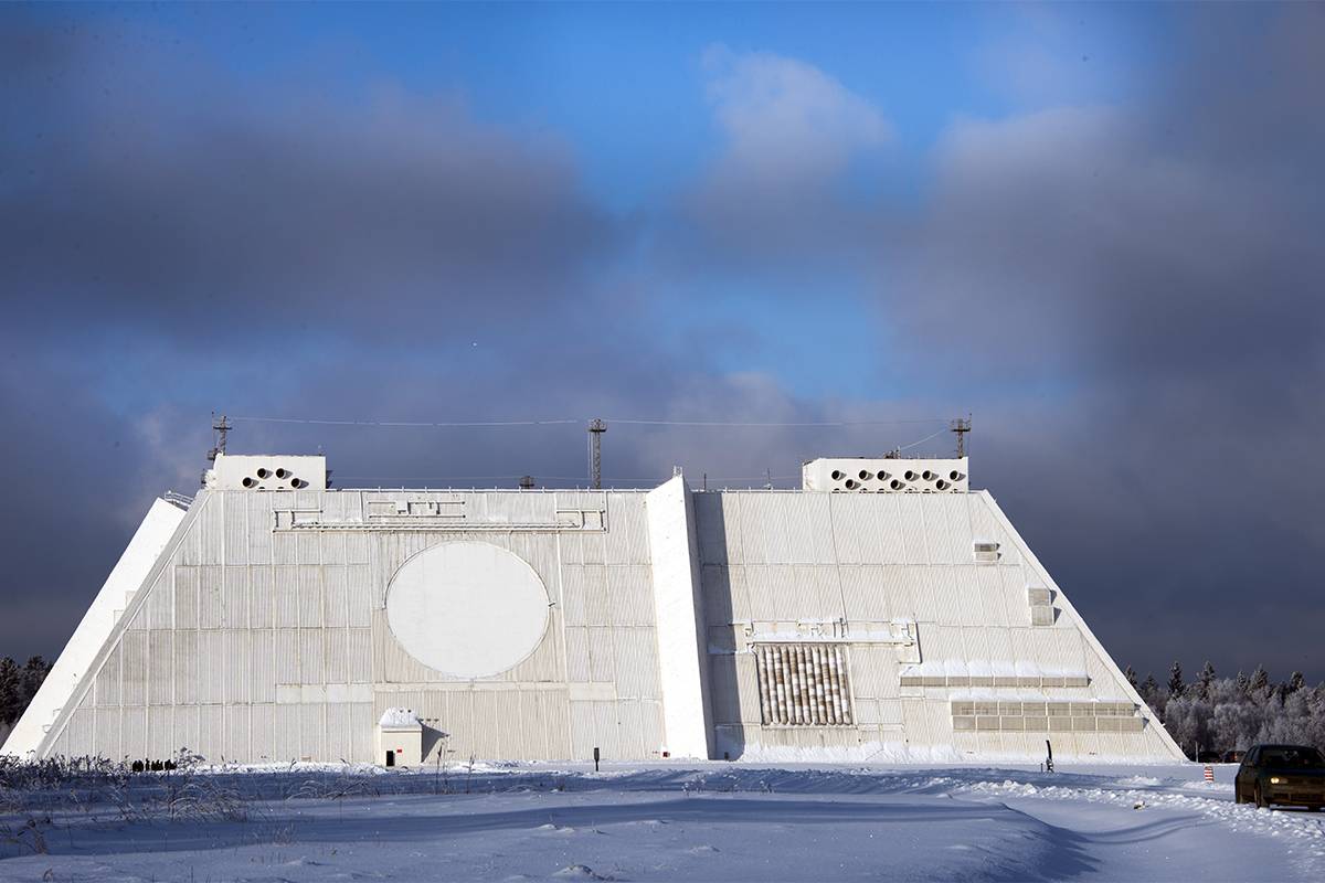
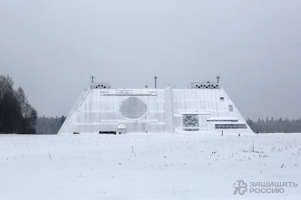
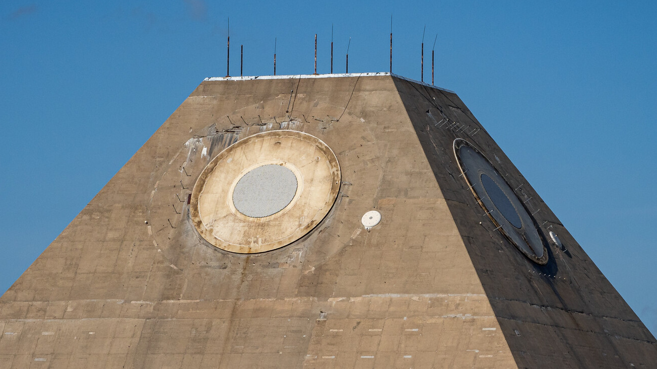
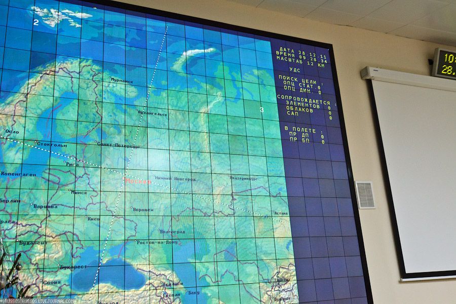
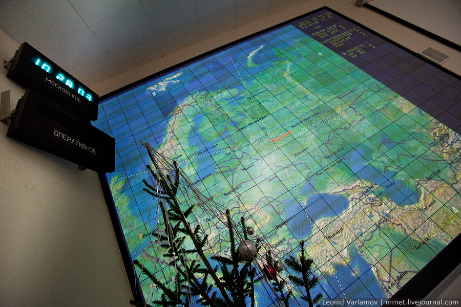
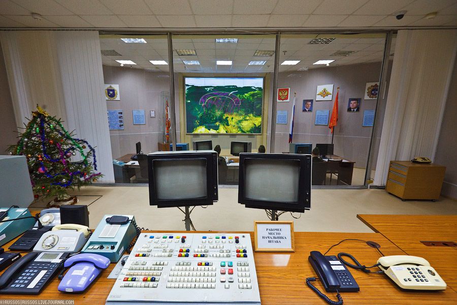
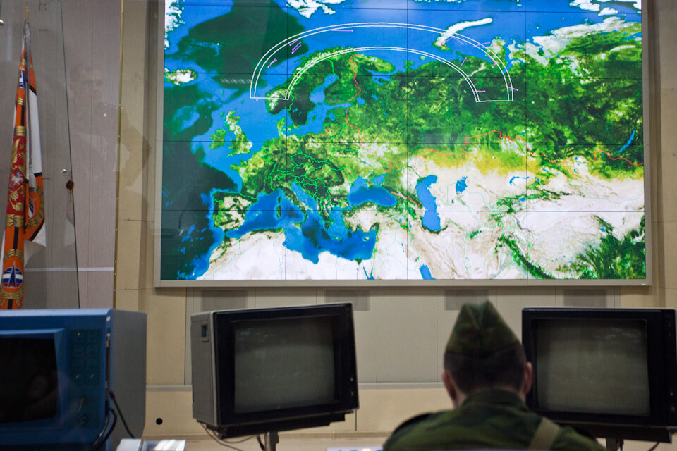
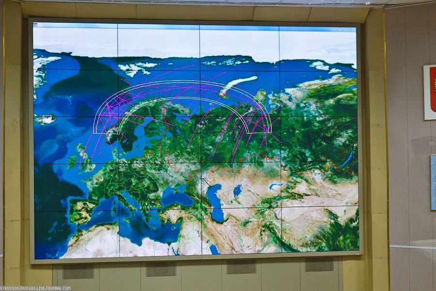
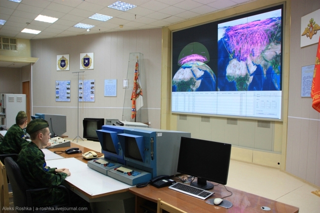
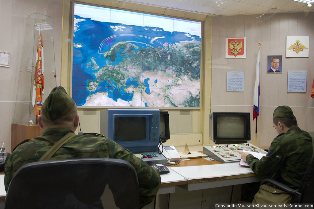
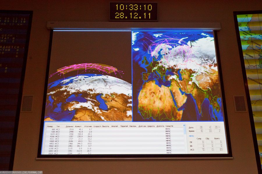
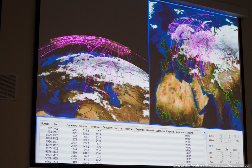
The radar complex operates on the dual redundancy principle where three identical devices are installed: Operating Device Due to the massive power of the radar, biological fences surround it to protect personnel in the open from the radar and there are underground tunnels over 1 km in length connecting the radar complex with the outer perimeter; to enable personnel to move in and out while the radar is in operation. [IMAGE OF FACILITY ALERT LEVELS 1 | 2 | 3] Deeper Technical DetailsEach side of the pyramid contains a 18m circular [250m2] active phased array antenna; which is driven by 72 modules arranged in a 8 x 9 configuration. The modules themselves are about 8 meters long and weigh 3000 kg. [IMAGE OF MAIN CIRCULAR RADAR] [IMAGE OF RADAR MODULES – 1 | 2 | 3 | 4 | 5 | 6 | 7 | 8 ] Next to each 18m antenna, separated by a “gate” is a smaller 10.4m x 10.4m [108.16m2] square phased array antenna. [IMAGE OF SECONDARY SQUARE RADAR] [IMAGE SHOWING SEPARATION “GATES” IN BETWEEN RADARS] Analysis of imagery of this antenna reveals several things: First, If we assume that this smaller antenna has the same antenna gain and efficiency as the larger 4000 MHz antenna (it has to be able to control missiles out to maximum range) the frequency of it has to be around 6140 MHz. This eliminates Russian-language theories of it being the DON-2N transmitter antenna (similar to the older S-225 FLAT TWIN radar), and confirms that it is the missile telemetry radar. (NOTE: Confirmation that DON-2N has an 18m diameter radar is obtained via scaling off THIS image) Second, looking at the old SAFEGUARD MSR (IMAGE) reveals that you don't need a very large antenna for simple missile telemetry – the MSR missile telemetry transmitter was only 1.2~m diameter [1.31m2 area] versus the MSR array's 3.96m diameter [12.3m2 area], a ratio of 9.38x. If that secondary radar was truly for missile telemetry only and had the same aperture ratio (9.38) as on the Safeguard MSR, it would be about 26~ m2 in area. Instead, it's a massive 108 m2. This means that it's more than just a missile telemetry transmitter; but a functionally separate radar that's lumped in with the larger 18m Phased Array as part of the 5N20 Radar Complex. Third, the fact that the Don-2N radar could see 5 cm metal spheres at a range of 1500 to 2000 km during the 1994-1995 ODERACS (Orbital Debris Radar Calibration Sphere) shuttle experiments [STS-60 & STS-63] confirms that the secondary arrays are operating at 6135 MHz (4.89 cm), and can see those 5 cm spheres. This has massive implications for decoy discrimination. Elsewhere, very little is actually known about the radar other than vague public figures of it consuming 250 MW; but we can estimate using the early AN/SPY-1 radars, which pushed 4.2 MW through 12m2 apertures, for 0.35 MW/m2 as a baseline: Primary: 87.5 MW This is backed up by statements from radar designers: «Сервант» состоял из трех последовательно включенных СВЧ-каскадов усиления с выходной импульсной мощностью мегаваттного уровня. “The "Servant" consisted of three series-connected microwave amplification stages with a megawatt-level pulsed output power.” 87.5 MW divided by 72 modules = 1.21 MW per module, which aligns with the above; and shows my estimates are within order of magnitude credibility. Given that the entire complex is cited as requiring 250 MW; this means that there is enough generating capacity on site to drive two faces simultaneously at full power, which makes sense as two faces would provide coverage of a significant portion of likely incoming ballistic missile trajectories; and the complex can timeshare the faces to provide 360 degree track updates; with preference given to the faces facing the greatest incoming attack threat at that moment. [IMAGE OF FACE ORIENTATIONS – 1 | 2] Most of the time, the 5N20 Radar Complex is in standby mode; undoubtedly due to the massive power draw of the full complex, and also to preserve the operating life time of the vacuum-tube based T/R modules; with the BMD C3I complex relying on other early warning radars around Russia to provide it with situational awareness. When combat mode is initiated, sirens sound on the exterior grounds, warning personnel that they have presumably 15 to 20 seconds to reach shelter before the radar lights off. Internally, the complex switches to autonomous power from nearby on-site generators, and the cooling systems are activated. If the cooling system fails, water is drawn from on-site wells into the emergency cooling system and then dumped externally onto the complex grounds. [Engagement
Sequence (#1) as seen from the A-135 System's
Commander's Office] Condensed DON-2N Specifications: Four Faces installed at 60 deg, 150 deg, 240 deg and 330 deg; giving 360 deg coverage when combined. Each face has a primary and secondary antenna: PRIMARY: 18m diameter circular phased array [250m2 aperture] operating at 4000 MHz Frequency (7.5 cm); 87.5 MW Peak SECONDARY: 10.4m x 10.4m square phased array [108m2 aperture] operating at 6135 Mhz Frequency (4.89 cm); 37.8 MW Peak The primary radar is an early active electronically steeered phased array -- it contains 72 T/R modules each capable of providing 1+ MW power, and can form 30 beams at once; along with having fully digital radar signals processing. Only enough power/cooling is installed at the site for two faces to be operated simultaneously; presumably the site "time shares" faces at full power. Estimated Ranges against the Standard Radar Target (0.005m2) are 2,500 km for the SECONDARY radar; it's likely the PRIMARY can see just as far. PRS-1 / 53T6 [ПРС-1 (53Т6)] Endo-Atmospheric Interceptor Missile (ABM-3A GAZELLE)Length: 12~ m NOTE: There are rumors that the Soviets experimented/thought about developing a 53T6 Silo Launcher system utilizing a drum-type revolver system for combat reloading of ABM silos to stay within the limitations of the ABM treaty. PRS-1M (53T6M) [ПРС-1М (53Т6М)] Modernized GAZELLEAcceleration: 300G longitudinal. NOTES: Tested circa 2018. Has kill zone that is nearly 50 percent larger in altitude and range than the 53T6. It can reliably intercept enemy ICBM warheads at altitudes well above 50 kilometers. Approximately 1.33 times faster (vBO) than 53T6. Smaller warhead. 51T6 Exo-Atmospheric Interceptor Missile (ABM-4 GORGON)First Stage: 41A6 Solid Motor, 5 second burn
time NOTES: Modernized A-350R [А-350Р]. Preliminary design was completed in 1973-74 with finalization in 1976. Can be retargeted mid-flight. |
|
Geodetic Center of all A-135 + 53T6 Launcher
Sites: |
||||
|---|---|---|---|---|
|
Site Name |
Launcher Count |
Decimal Coordinates |
DMS Coordinates |
|
|
Don-2N (PILL BOX) Radar |
Pushkino Phased-Array Radar |
N/A |
56.17325, 37.76937 |
56°10'23.715" N 37°46'9.735" E |
|
Korolev Launch Site (Former SA-2 Site) |
MOSKVA ABM LAUNCH SITE B06 |
12 x 53T6 Silos |
55.87778, 37.89333 |
55°52'40" N 37°53'36" E |
|
Skhodnya Launch Site (Former SA-2 Site) |
MOSKVA ABM LAUNCH SITE B31 |
16 x 53T6 Silos |
55.90139, 37.30806 |
55°54'5" N 37°18'29" E |
|
Vnukovo Launch Site (Former SA-2 Site) |
MOSKVA ABM COMPLEX B22 |
12 x 53T6 Silos |
55.62583, 37.39028 |
55°37'33" N 37°23'25" E |
|
Lytkarino Launch Site (Former SA-2 Site) |
MOSKVA SAM SITE B16-2 |
16 x 53T6 Silos |
55.57750, 37.77111 |
55°34'39" N 37°46'16" E |
|
Sofrino Launch Site (Brand New Site) |
MOSKVA ABM LAUNCH SITE C02 |
12 x 53T6 Silos |
56.18109, 37.78759 |
56°10'51.918" N 37°47'15.334" E |
|
Sergiyev Posad-15 Launch Site [Retired c.2003] |
MOSKVA ABM LAUNCH COMPLEX E05 |
8 x 51T6 Silos |
56.24423, 38.57589 |
56°14′39″N 38°34′33″E |
|
Naro-Fominsk-10 Launch Site [Retired c.2003] |
MOSKVA ABM LAUNCH COMPLEX E24 |
8 x 51T6 Silos |
55.34954, 36.48020 |
55°20′58″N 36°28′49″E |
